

Learn how to use a digital multimeter with confidence: where the probes go, what the symbols mean, how to measure voltage, continuity, resistance and current, and which mistakes can damage your meter or create an electrical hazard.
What a digital multimeter does
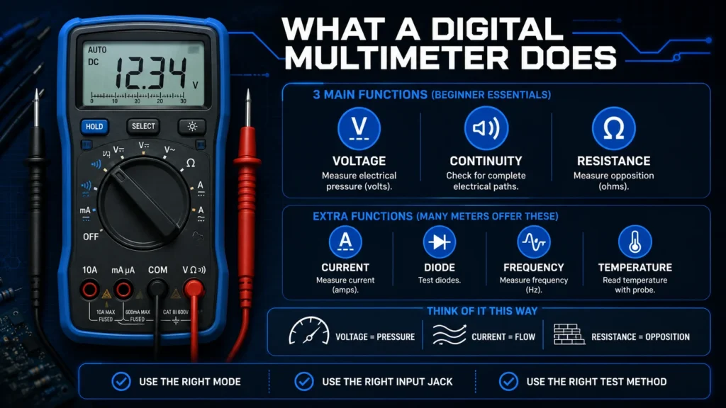
A digital multimeter, often called a DMM, is a handheld instrument that measures electrical values. The beginner functions you will use most often are voltage, continuity and resistance. Many meters can also measure current, test diodes, check frequency and read temperature with the right probe.
Think of voltage as electrical pressure, current as electrical flow, and resistance as opposition to that flow. You do not need advanced theory to troubleshoot common jobs, but you do need the right mode, the right input jack, and the right test method for the circuit.
The beginner-friendly picture
For nearly every first test, plug the black lead into COM and the red lead into VΩ. Select voltage for a powered battery or circuit. Select continuity or resistance only after disconnecting power. Check your meter manual because symbols, jack labels and limits vary by model.
Main parts and multimeter symbols explained
Your meter may look different, but these controls appear on most digital multimeters. A dial can be auto-ranging, where the meter chooses the range, or manual-ranging, where you choose a range above the value you expect.
Display and selector dial
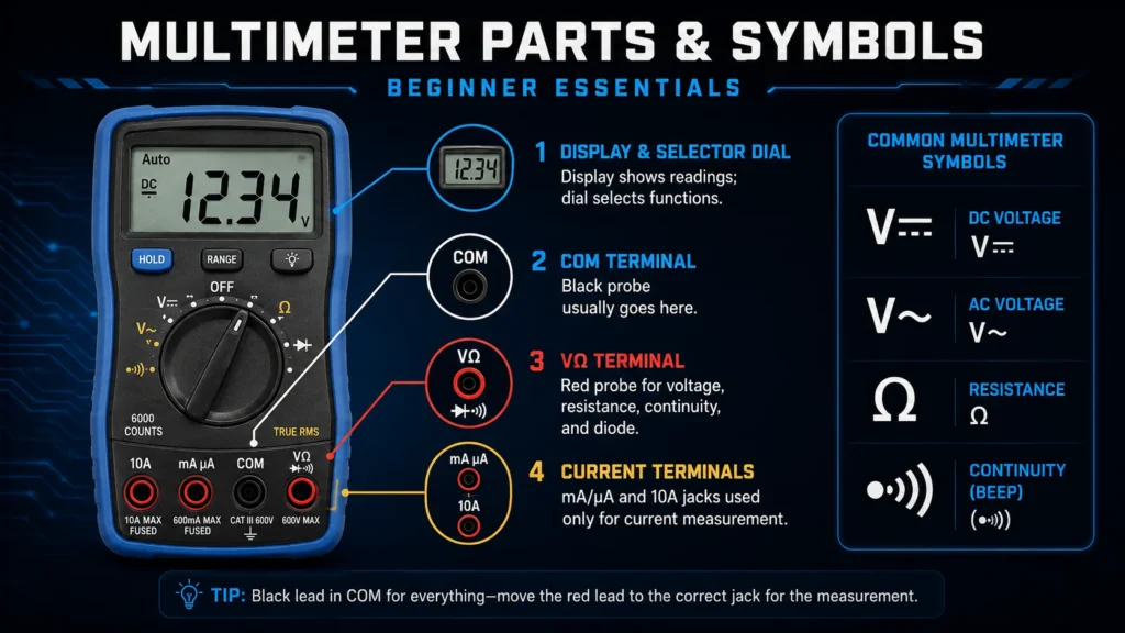
The display shows the reading. The dial selects DC voltage (V⎓), AC voltage (V~), resistance (Ω), continuity (sound-wave symbol), and other functions.
COM terminal
COM means common. The black probe normally stays in this jack for all ordinary measurements, including voltage, resistance and continuity.
VΩ terminal
The red probe commonly goes here for voltage, resistance, continuity and diode tests. Exact printed symbols vary, so read the front-panel labels.
Current terminals
Many meters provide a fused mA or µA jack and a separate high-current 10A jack. These are used only for current measurement and have strict limits.
Where do the red and black probes go?
Probe placement is one of the most important digital multimeter settings. Read your exact meter’s labels and manual before testing. The table below describes the common arrangement, not a universal wiring diagram.
| Meter jack | Probe | Typical use | Important note |
|---|---|---|---|
| COM | Black | Common reference for nearly every measurement | Leave the black probe here unless your manual says otherwise. |
| VΩ / Hz | Red | Voltage, resistance, continuity, diode and often frequency | This is the normal red-probe jack for beginner testing. |
| mA / µA | Red | Small current measurements in series | Usually fused; check the stated maximum and fuse rating. |
| 10A / A | Red | Higher current measurements in series | Often time-limited. Return the red lead to VΩ after testing. |
The port mistake that blows fuses
If the red probe is in a current jack and you touch both probes across a battery, power supply or outlet, the meter can create a near-short circuit. This can blow the internal fuse, damage the meter or cause an arc. Before every new task, pause and confirm: red lead in the correct jack, dial in the correct mode.
How to measure voltage with a multimeter
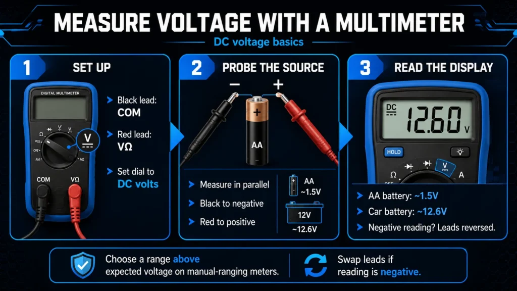
Voltage is measured in parallel: touch the probes across the two points whose voltage difference you want to know. For basic DC tests, the black probe goes to negative or ground and the red probe goes to positive.
Set up for DC voltage
Plug black into COM and red into VΩ. Turn the dial to V⎓, sometimes shown as a solid line above a dashed line. On a manual-ranging meter, choose a range above what you expect; use 20V for a 1.5V, 9V or 12V source if available.
Touch the probes across the source
For a battery, touch black to the negative terminal and red to the positive terminal. A healthy fresh AA alkaline battery may read around 1.5V with no load. A 12V car battery at rest is commonly near 12.6V when fully charged.
Read and interpret the display
A negative reading on a DC test usually means the leads are reversed, not that the meter is broken. Swap the probe positions if you want a positive number. Compare results with the device specification and consider whether the source is under load.
How to measure AC voltage
Select V~ for alternating current. AC has no fixed polarity, so probe direction does not matter. Live mains outlets and panels can be hazardous; only test them if you understand the hazards, use a meter and leads with an appropriate CAT rating, and follow local electrical safety practices. Beginners can start with low-voltage AC adapters instead.
How to test a battery
Use DC voltage mode. Test the battery directly at its terminals, keeping the probes from touching each other. A voltage reading is a useful first check, but a battery can read normally with no load and still perform poorly in a device. For a final diagnosis, test under the manufacturer-recommended load where appropriate.
Continuity, resistance and fuse testing
De-energize the circuit before continuity or resistance testing. Disconnect batteries, unplug power supplies and allow stored energy to discharge as instructed by the equipment manufacturer. Measuring an in-circuit component can be misleading because parallel paths affect the reading.
Test continuity
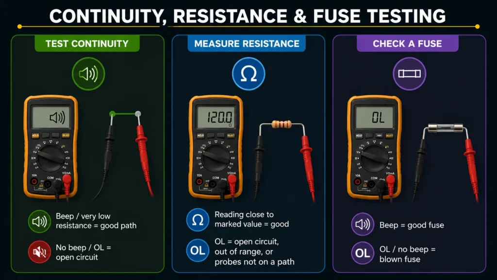
Select continuity, often combined with the diode setting. Touch the probes together first; the meter should beep or show very low resistance. Then test a disconnected wire, switch, connector or fuse. A beep usually indicates a low-resistance path.
Measure resistance
Select Ω and place the probes across the unpowered component. A resistor should read close to its marked value within tolerance. OL may mean an open circuit, a value above the selected range, or probes that are not connected to a path.
Check a fuse
Remove the fuse or isolate one side when possible. In continuity mode, a good fuse generally beeps; a blown fuse generally shows OL or no beep. Replace it only with the manufacturer-specified type, current rating and voltage rating.
How to measure current safely
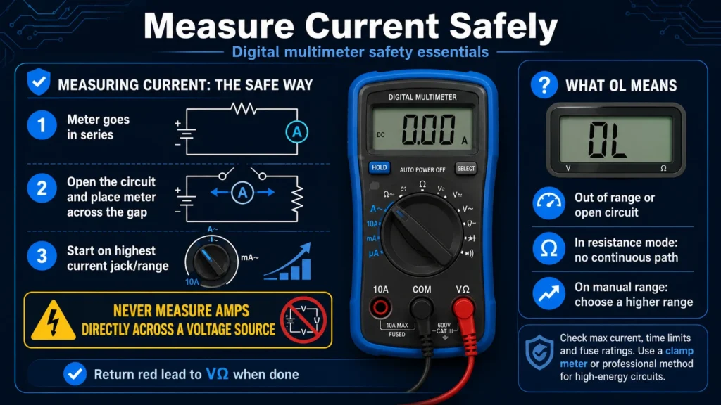
Current is different from voltage: the meter must become part of the circuit, in series, so current flows through the meter. Open the circuit at a suitable point and connect the probes across that opening. This is an advanced step because an incorrect setup can damage equipment or the meter.
Never measure amps directly across a voltage source
Start at the highest appropriate current jack and range, then move only if your manual permits it. Check maximum current, time limits and fuse ratings. For automotive, mains or high-energy circuits, a clamp meter or professional method may be safer. Return the red probe to VΩ when finished so the meter is ready for the next test.
What does OL mean on a multimeter?
OL, O.L. or overload commonly means the reading is outside the selected range or the meter sees an open circuit. In resistance mode, it often means no continuous path exists between the probes. In voltage mode on a manual-range meter, select a higher range. Always use your manual as the final authority for its display codes.
Digital multimeter FAQs and common mistakes
Can I damage a multimeter by using the wrong setting?
Yes. The most common errors are using a current jack for a voltage test, exceeding the meter’s input rating, measuring resistance on a powered circuit, and using damaged leads. Inspect the meter, probe insulation and exposed tips before use. Follow the maximum voltage, current and CAT ratings printed on the meter and leads.
Why does my meter show a negative voltage?
On a DC measurement, the negative sign usually means your red probe is on the lower-potential side and your black probe is on the higher-potential side. For a battery, swap the probes: black to negative and red to positive. The magnitude of the reading is still useful.
Is it safe to test a wall outlet with a multimeter?
Mains testing is not a casual beginner task. It requires an appropriately CAT-rated meter and leads, correct AC voltage mode, safe probe handling and an understanding of the installation. If you are unsure, work with a qualified electrician. Never use damaged equipment or exceed stated input ratings.