

A comprehensive guide to help you define a gear, understand each gear type, and choose the right one for your application.
Gears are among the most fundamental components in mechanical engineering. From the transmission in your car to the hands of a wristwatch, gears are everywhere — quietly transmitting power, changing speed, and altering direction. But what exactly is a gear, and why are there so many different types?
In this article, we define a gear in clear, straightforward language. We then explore the major gear types, explain how each one works, and outline where they are used in real-world applications. Whether you are an engineering student, a technician, or simply curious, this guide will give you a solid understanding of the gear definition and practical knowledge to identify and select gears confidently.
What Is a Gear? — Gear Definition
To define a gear simply: a gear is a rotating machine element with cut teeth that meshes with another toothed component to transmit torque and motion between shafts. Gears change the speed, direction, or magnitude of rotational force (torque) in a mechanical system.
Gear Definition: A gear is a toothed wheel that works with other toothed parts to alter the speed, torque, or direction of mechanical energy. — Based on AGMA (American Gear Manufacturers Association) standards.
The gear definition can also be stated as: a cylindrical or conical body with teeth formed on its surface that engages with a mating gear to form a gear pair. When two gears mesh, the smaller gear is called the pinion and the larger is called the wheel or gear. The ratio of their teeth determines the gear ratio — a key factor in mechanical design.
How Do Gears Work?
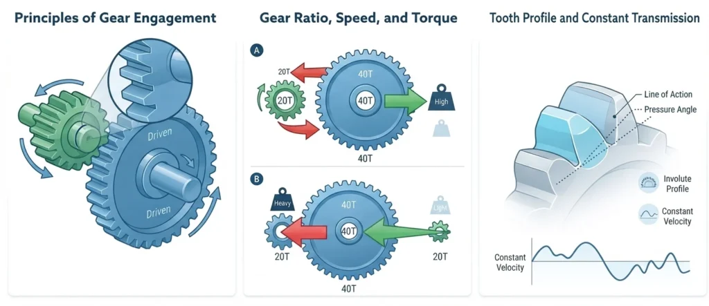
Gears work on a simple principle: when two toothed wheels mesh together, rotating one gear (the driver) causes the other (the driven gear) to rotate as well. The interlocking teeth ensure positive engagement — meaning no slipping occurs, unlike belt drives.
The gear ratio determines how speed and torque are exchanged. If a small gear with 20 teeth drives a larger gear with 40 teeth, the output speed is halved but the torque is doubled. This is the fundamental trade-off that makes gears so useful in engineering: you can convert high-speed, low-torque input into low-speed, high-torque output (or vice versa).
Gears transmit power through the contact force between meshing teeth. The tooth profile — most commonly an involute curve — ensures smooth, constant-velocity transmission. This involute geometry is the standard in modern gear design because it maintains a constant pressure angle regardless of the center distance between shafts.
Types of Gears
1. Spur Gears
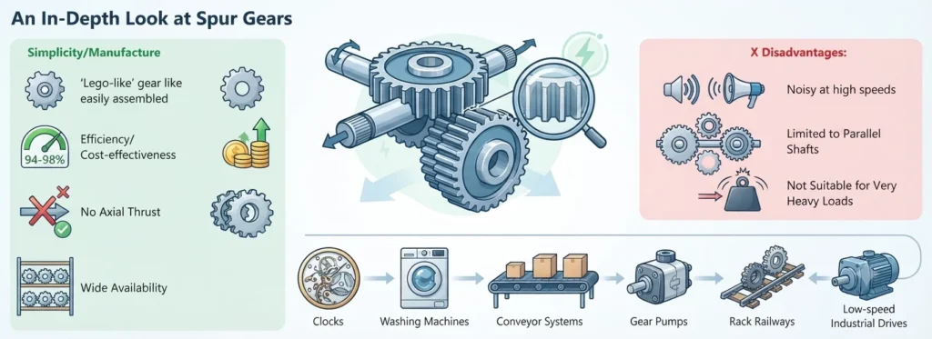
Spur gears are the simplest and most common gear type. They have straight teeth cut parallel to the gear’s axis of rotation. Two spur gears mesh on parallel shafts, making them easy to design and manufacture.
✓ Advantages:
Simple design, easy to manufacture, high efficiency (94–98%), no axial thrust, cost-effective, widely available in standard sizes.
✗ Disadvantages:
Noisy at high speeds due to sudden full-face tooth contact, limited to parallel shaft arrangements, not suitable for very heavy loads at high speeds.
Common uses: Clocks, washing machines, conveyor systems, gear pumps, rack railways, and low-speed industrial drives.
2. Helical Gears
Helical gears have teeth cut at an angle (helix angle) to the axis of rotation. This angled design means multiple teeth are in contact simultaneously, resulting in smoother and quieter operation compared to spur gears. This gear type is preferred for high-speed applications.
✓ Advantages:
Quieter and smoother than spur gears, can handle heavier loads, gradual tooth engagement reduces shock, suitable for high-speed operation.
✗ Disadvantages:
Generate axial (thrust) loads requiring thrust bearings, slightly less efficient due to sliding contact, more expensive to manufacture.
Common uses: Automotive transmissions, industrial gearboxes, turbines, elevators, and power generation equipment.
3. Bevel Gears
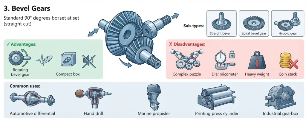
Bevel gears have cone-shaped bodies with teeth cut along the conical surface. They are designed to transmit motion between shafts that intersect — most commonly at 90°, though other angles are possible. Sub-types include straight bevel, spiral bevel, and hypoid gears.
✓ Advantages:
Can change the direction of shaft rotation, compact design for right-angle drives, spiral bevel types operate smoothly and quietly.
✗ Disadvantages:
Complex to manufacture, require precise mounting and alignment, generate significant thrust loads, more expensive than spur gears.
Common uses: Automotive differentials, hand drills, marine drives, printing presses, and power plant equipment.
4. Worm Gears
A worm gear system consists of a worm (a screw-like gear) meshing with a worm wheel. The worm drives the wheel, providing a very high gear reduction ratio in a compact space. This gear type is unique because the worm can turn the wheel, but in most cases the wheel cannot turn the worm — a property called self-locking.
✓ Advantages:
Very high reduction ratios (up to 100:1) in a single stage, self-locking capability, quiet operation, compact design, good for speed reduction.
✗ Disadvantages:
Low efficiency (40–90%) due to sliding friction, generates significant heat, requires good lubrication, the worm wheel material must be softer (typically bronze).
Common uses: Elevator drives, conveyor systems, tuning instruments, gate operators, steering mechanisms, and packaging machinery.
5. Rack and Pinion
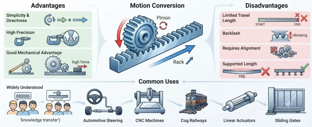
A rack and pinion converts rotational motion into linear motion (or vice versa). The rack is essentially a gear with teeth laid out in a straight line, while the pinion is a small cylindrical gear that meshes with it. As the pinion rotates, the rack moves in a straight line.
✓ Advantages:
Simple and direct conversion between rotary and linear motion, high precision, good mechanical advantage, widely understood mechanism.
✗ Disadvantages:
Limited travel length, backlash can affect precision, requires proper alignment, rack must be supported along its length.
Common uses: Automotive steering systems, CNC machines, railways (cog railways), linear actuators, and sliding gates.
6. Planetary (Epicyclic) Gears
A planetary gear system (also called epicyclic) consists of a central sun gear, multiple planet gears that revolve around it, and an outer ring gear (annulus). By holding different elements stationary, you can achieve different gear ratios from the same compact assembly.
✓ Advantages:
Extremely compact, high power density, coaxial input/output shafts, multiple ratio options from one unit, very high efficiency (97%+), distributes load across multiple planets.
✗ Disadvantages:
Complex design, expensive to manufacture, requires precision assembly, lubrication is critical, difficult to repair.
Common uses: Automatic transmissions, wind turbine gearboxes, aircraft engines, hybrid vehicle drives, robotic joints, and industrial speed reducers.
7. Herringbone (Double Helical) Gears
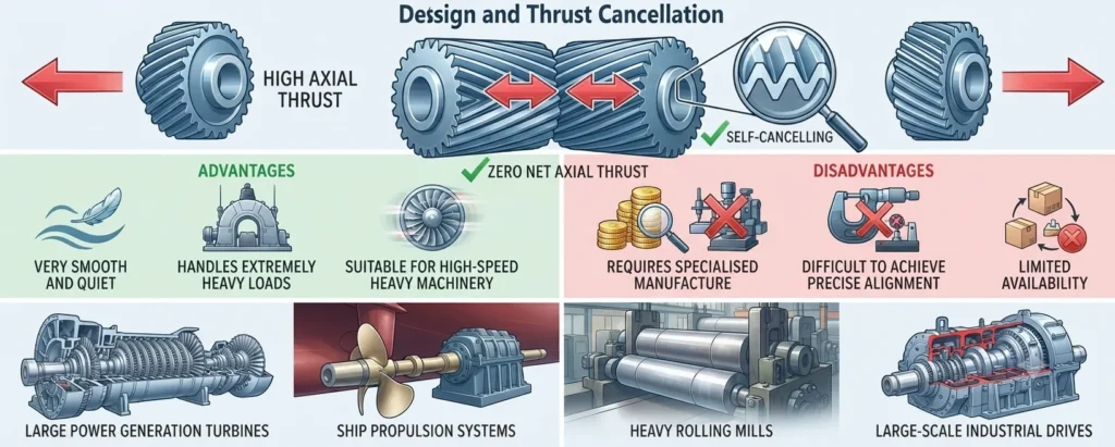
Herringbone gears are essentially two helical gears with opposite helix angles placed side by side on the same gear body. This design cancels out the axial thrust that single helical gears produce, combining the smooth operation of helical gears with the thrust neutrality of spur gears.
✓ Advantages:
No axial thrust (self-cancelling), very smooth and quiet, handles extremely heavy loads, suitable for high-speed heavy machinery.
✗ Disadvantages:
Very expensive to manufacture, requires specialised machining, difficult to achieve precise alignment of both helical sections, limited availability.
Common uses: Large power generation turbines, ship propulsion systems, heavy rolling mills, and large-scale industrial drives.
Gear Type Comparison Table
| Gear Type | Axis Orientation | Noise Level | Efficiency | Best For |
|---|---|---|---|---|
| Spur | Parallel | High | High (94–98%) | Low-speed, simple drives |
| Helical | Parallel / Crossed | Low | High (94–98%) | High-speed, heavy loads |
| Bevel | Intersecting | Moderate | High (93–97%) | Changing shaft direction |
| Worm | Non-intersecting (90°) | Very low | Low (40–90%) | High reduction, self-locking |
| Rack & Pinion | Linear–rotary | Moderate | High | Linear motion conversion |
| Planetary | Coaxial | Low | Very high (97%+) | Compact high-torque drives |
| Herringbone | Parallel | Very low | High | Heavy industrial machinery |
What Materials Are Gears Made From?
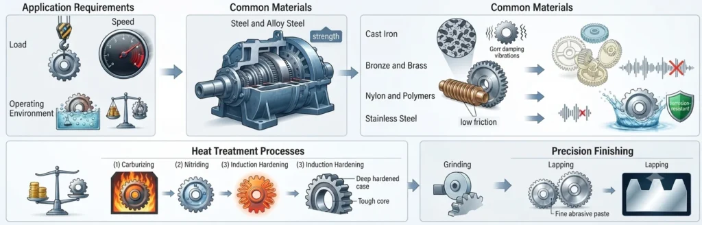
Gear material selection depends on the application requirements — load, speed, operating environment, and cost. Common materials include: Steel and alloy steel (most common for high-strength industrial gears), Cast iron (good wear resistance, vibration damping), Bronze and brass (used for worm wheels due to low friction against steel), Nylon and other polymers (lightweight, quiet, used in low-load consumer products), and Stainless steel (for corrosive environments).
Heat treatment processes such as carburizing, nitriding, and induction hardening are used to increase surface hardness and extend gear life. For critical applications in aerospace or motorsport, gears may be ground and lapped to achieve mirror-finish tooth surfaces.
Frequently Asked Questions
What is the simplest way to define a gear?
A gear is a toothed rotating machine part that meshes with another toothed part to transmit torque and change speed or direction of motion. Think of it as a wheel with precisely shaped teeth around its edge.
Which gear type is best for high-speed applications?
Helical gears are generally the best choice for high-speed applications because their angled teeth engage gradually, producing less noise and vibration. For very high speeds with compact packaging, planetary gear systems are also excellent.
What is the difference between a spur gear and a helical gear?
Spur gears have straight teeth parallel to the shaft axis, while helical gears have teeth cut at an angle. Helical gears are quieter and can carry more load, but they produce axial thrust and are more expensive to manufacture.
Can gears increase both speed and torque simultaneously?
No. Gears obey the law of conservation of energy. When gears increase torque (using a larger driven gear), speed decreases proportionally. When speed increases (using a smaller driven gear), torque decreases. You always trade one for the other.
What does ‘gear ratio’ mean?
Gear ratio is the relationship between the number of teeth on two meshing gears. It determines how much the speed and torque change. A gear ratio of 3:1 means the output shaft turns three times slower but with three times more torque than the input shaft.
Conclusion
Understanding how to define a gear and recognizing the different gear types is essential knowledge for anyone working in mechanical engineering, manufacturing, or industrial maintenance. Each gear type — from the simple spur gear to the complex planetary system — has specific strengths that make it ideal for particular applications.
When selecting a gear for a project, consider the shaft arrangement, required speed and torque, noise constraints, efficiency needs, and budget. With the gear definition and type comparisons provided in this guide, you are now equipped to make informed decisions and communicate confidently about gears in any engineering context.