

A practical introduction to oscilloscopes: see electrical signals, set up a stable waveform, measure it with confidence, and avoid common probing mistakes.
An oscilloscope is a test instrument that draws voltage changes over time. Unlike a multimeter’s single number, it lets you inspect a signal’s amplitude, frequency, timing, noise, and shape.
If you work with Arduino boards, power supplies, audio circuits, sensors, or repairs, oscilloscopes can answer questions that a multimeter cannot. Is a 5 V rail actually steady? Is a PWM output switching? Does an audio signal clip? The display gives you evidence rather than a guess.
What does an oscilloscope measure?
Most oscilloscopes measure voltage at their input and plot it vertically against time plotted horizontally. The resulting line is called a waveform. Its height shows voltage; its width shows how quickly the signal changes. A flat line usually represents steady DC, while repeating waves can represent AC, clock signals, pulse-width modulation, or data activity.
A scope does not automatically tell you why a waveform looks wrong. Automatic measurements are helpful checks, but understanding the displayed trace matters. Compare the result with the circuit’s expected voltage, timing, and shape before deciding what to change.
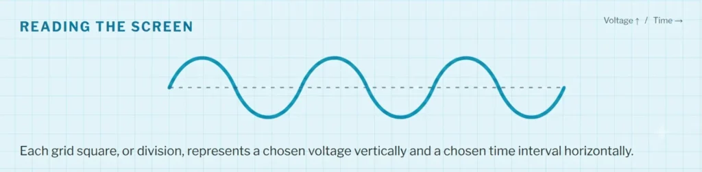
Volts per division
This control changes the vertical scale. At 1 V/div, a trace spanning three divisions is about 3 V peak-to-peak. Choose a scale that fills much of the screen without clipping.
Time per division
This control changes the horizontal view. At 1 ms/div, one screen division equals one millisecond. Slow it down to inspect a pulse; speed it up to see a slower repeating cycle.
The controls that make a waveform usable
Start with one channel, a sensible vertical scale, and a moderate time base. Then use triggering to stop the waveform from rolling across the display. A rising-edge trigger begins each sweep when the signal crosses your chosen trigger level going upward, making repeated signals appear stable.
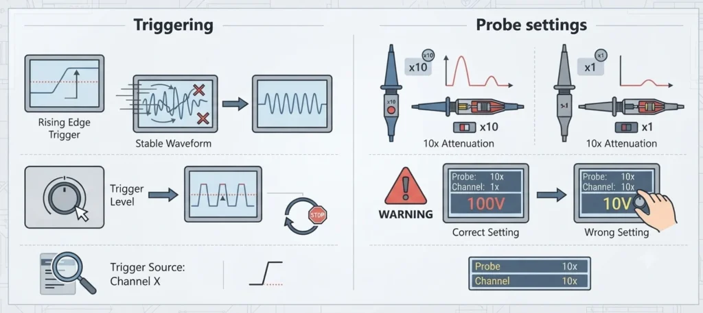
Triggering
Use trigger level to stop the roll
Set the trigger source to the channel you are viewing, select a rising edge, and place the trigger level near the middle of the signal. Adjust it until repeating cycles stop drifting.
Probe settings
Match 1× and 10× attenuation
A 10× probe reduces the voltage reaching the scope by a factor of ten and usually loads a circuit less. Set both the probe switch and channel menu to the same value, or every displayed voltage reading will be wrong.
A first low-voltage oscilloscope walkthrough
This demonstration reflects common lab practice for a built-in probe-compensation output or another known low-voltage test point. Exact button names and input limits vary by model, so check your oscilloscope and probe manuals before connecting anything.
- Inspect the probe and connect it to Channel 1. Set the probe and the channel menu to 10× if you are using a 10× probe.
- Connect the ground clip only to the instrument’s designated low-voltage ground point, then touch the probe tip to its calibration output or test signal.
- Start near 1 V/div and 1 ms/div. Press Auto Set if available, then refine the settings yourself so you learn what each division means.
- Choose an edge trigger on Channel 1 and move the trigger level until the square wave or sine wave stays still on the screen.
- Use cursors or automatic measurements to check voltage and frequency, then verify the result by counting divisions. A 1 kHz signal has a period of about 1 ms.
How to read common oscilloscope measurements
Use the grid as a quick reality check. Measurement accuracy depends on the scope, probe, calibration, selected scale, signal quality, and specified operating conditions. Read the manual for the exact model’s limits.
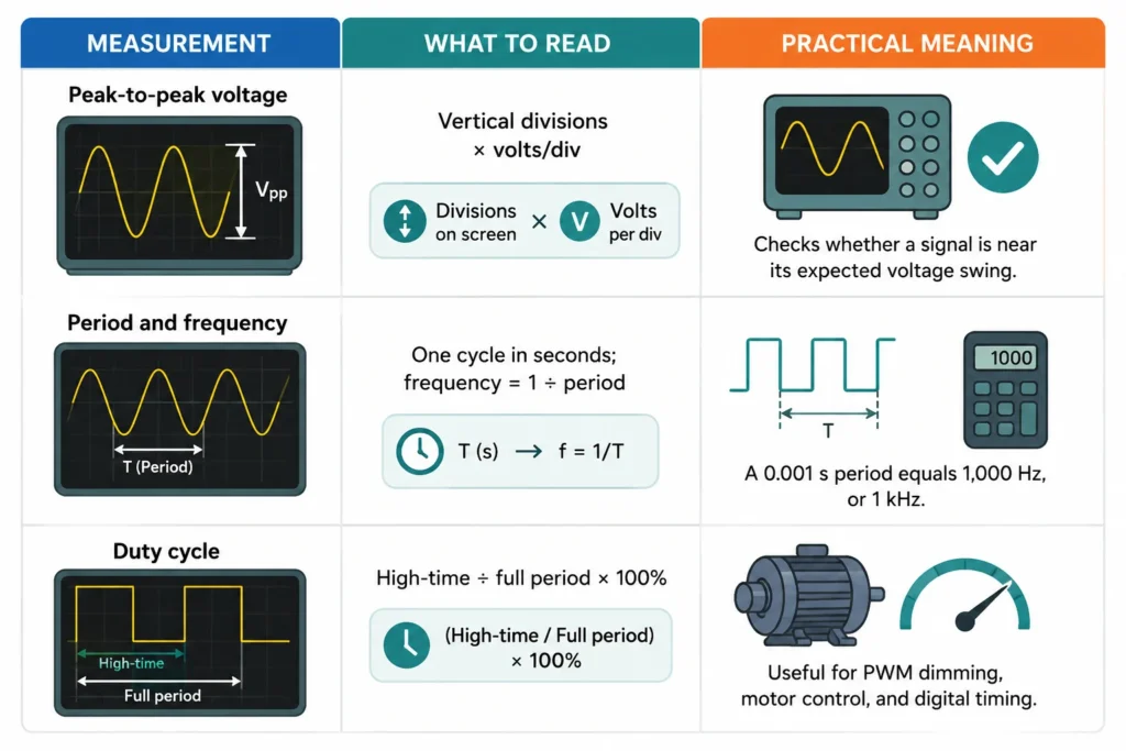
| Measurement | What to read | Practical meaning |
|---|---|---|
| Peak-to-peak voltage | Vertical divisions × volts/div | Checks whether a signal is near its expected voltage swing. |
| Period and frequency | One cycle in seconds; frequency = 1 ÷ period | A 0.001 s period equals 1,000 Hz, or 1 kHz. |
| Duty cycle | High-time ÷ full period × 100% | Useful for PWM dimming, motor control, and digital timing. |
Digital, analog, handheld, and USB oscilloscopes
For most beginners, a two-channel digital storage oscilloscope is the flexible starting point. It captures short events, saves waveforms, and provides measurements. The best option still depends on the signals you need to see and the safety category of the work.
Digital storage oscilloscope
The general-purpose choice for learning and repair. It captures waveforms in memory, supports measurements and triggering, and commonly offers two or more channels.
Analog oscilloscope
Older analog scopes can show live signals smoothly, but they lack modern storage and automated tools. They are valuable learning instruments when maintained and used safely.
Handheld or USB scope
Compact models can suit field work and simple signals, but check bandwidth, input rating, software support, sample rate, and isolation carefully before relying on one.
What to look for when buying an oscilloscope
Start with your real projects. Bandwidth describes the highest frequency range the scope can pass with specified attenuation; sample rate describes how often it samples the signal; memory depth determines how long it can record at a useful rate. For beginner microcontroller, audio, and low-speed repair work, two channels, clear controls, dependable triggering, quality probes, and honest documentation often matter more than a long feature list.
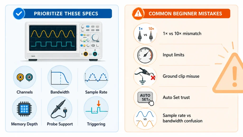
Prioritize these specifications
Check channel count, bandwidth, sample rate, memory depth, input-voltage limits, supported probe attenuation, trigger modes, display clarity, warranty, and calibration support. Confirm specifications for the exact model—not a product family headline.
Common beginner mistakes
Do not mismatch 1× and 10× settings, exceed an input rating, use a ground clip casually, trust Auto Set without checking scales, or mistake sample rate for bandwidth. Never use the scope as a substitute for appropriate high-voltage safety equipment.
Frequently asked questions
Can an oscilloscope replace multimeter?
Not completely. A multimeter is often quicker for steady voltage, resistance, continuity, and current checks. An oscilloscope is better when the value changes with time or when you need to see noise, ripple, timing, distortion, or pulse shape.
With bandwidth does a beginners need?
Choose bandwidth from the fastest signals you expect to investigate, allowing margin for edges and harmonics. A modest general-purpose digital scope can cover many beginner circuits, but consult manufacturer application notes for the signal types and accuracy you need.
Why does my waveform move across the screen?
The trigger is probably not finding the same point on each cycle. Confirm the trigger source, select a rising or falling edge, and move the trigger level to a voltage the signal reliably crosses. Then adjust the time base for a clear view.