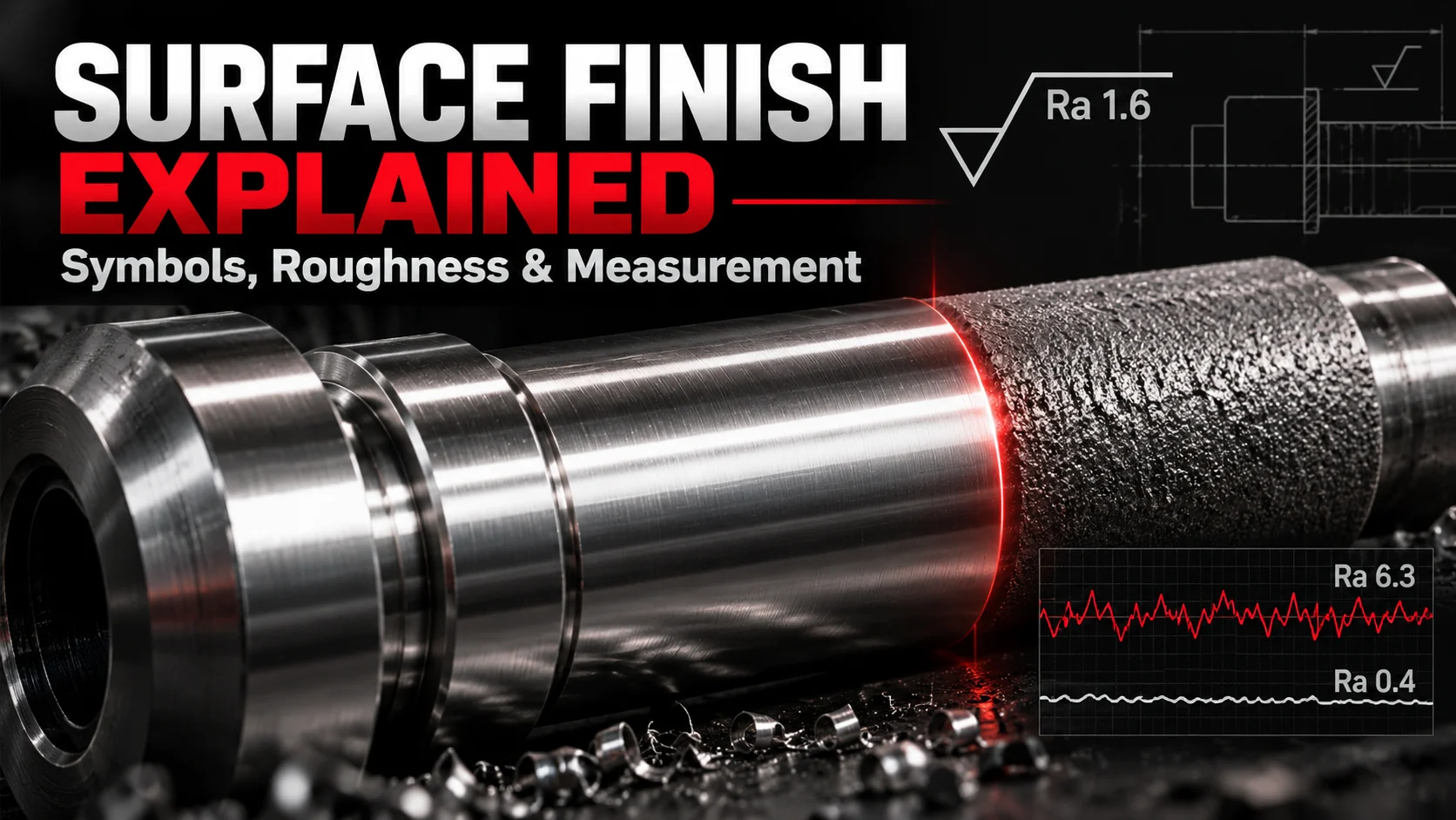

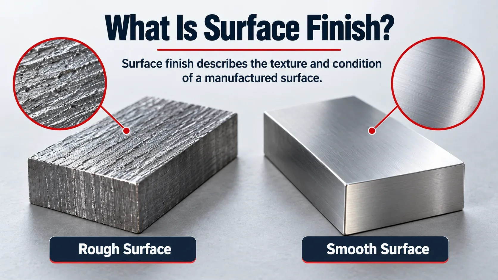
Surface finish describes the texture and condition of a manufactured surface. It influences how a component looks, fits, seals, wears, and performs in service.
In engineering and manufacturing, surface finish is commonly evaluated by measuring microscopic irregularities left behind by machining, grinding, polishing, casting, or other production processes.
This guide explains surface finish symbols, roughness values, Ra, Rz, measurement methods, machining processes, and practical engineering applications in a clear and practical way.
What Is Surface Finish?
Surface finish is a general term used to describe the physical characteristics of a manufactured surface. Even when a part looks perfectly smooth to the human eye, microscopic inspection usually reveals peaks, valleys, tool marks, and other irregularities.
These irregularities can be created by cutting tools, grinding wheels, polishing compounds, forming processes, vibration, tool wear, and material properties.
Engineers specify surface finish because the condition of a surface can directly affect component performance. A bearing journal, hydraulic sealing face, or precision shaft may need a much smoother and more controlled finish than a non-contact structural surface.
Surface Finish vs Surface Roughness
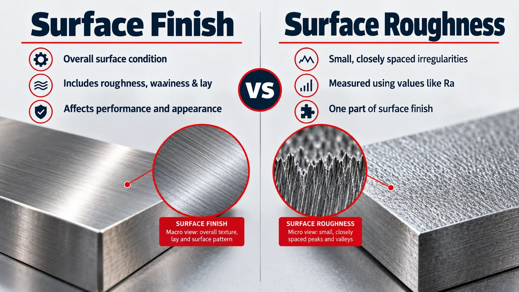
The terms surface finish and surface roughness are often used interchangeably, but they are not exactly the same.
Surface finish is the broader concept. Surface roughness is one part of surface texture and mainly refers to small, closely spaced irregularities on a surface.
| Term | Meaning |
|---|---|
| Surface Finish | The overall condition and texture of a manufactured surface. |
| Surface Roughness | Fine, closely spaced surface irregularities produced by the manufacturing process. |
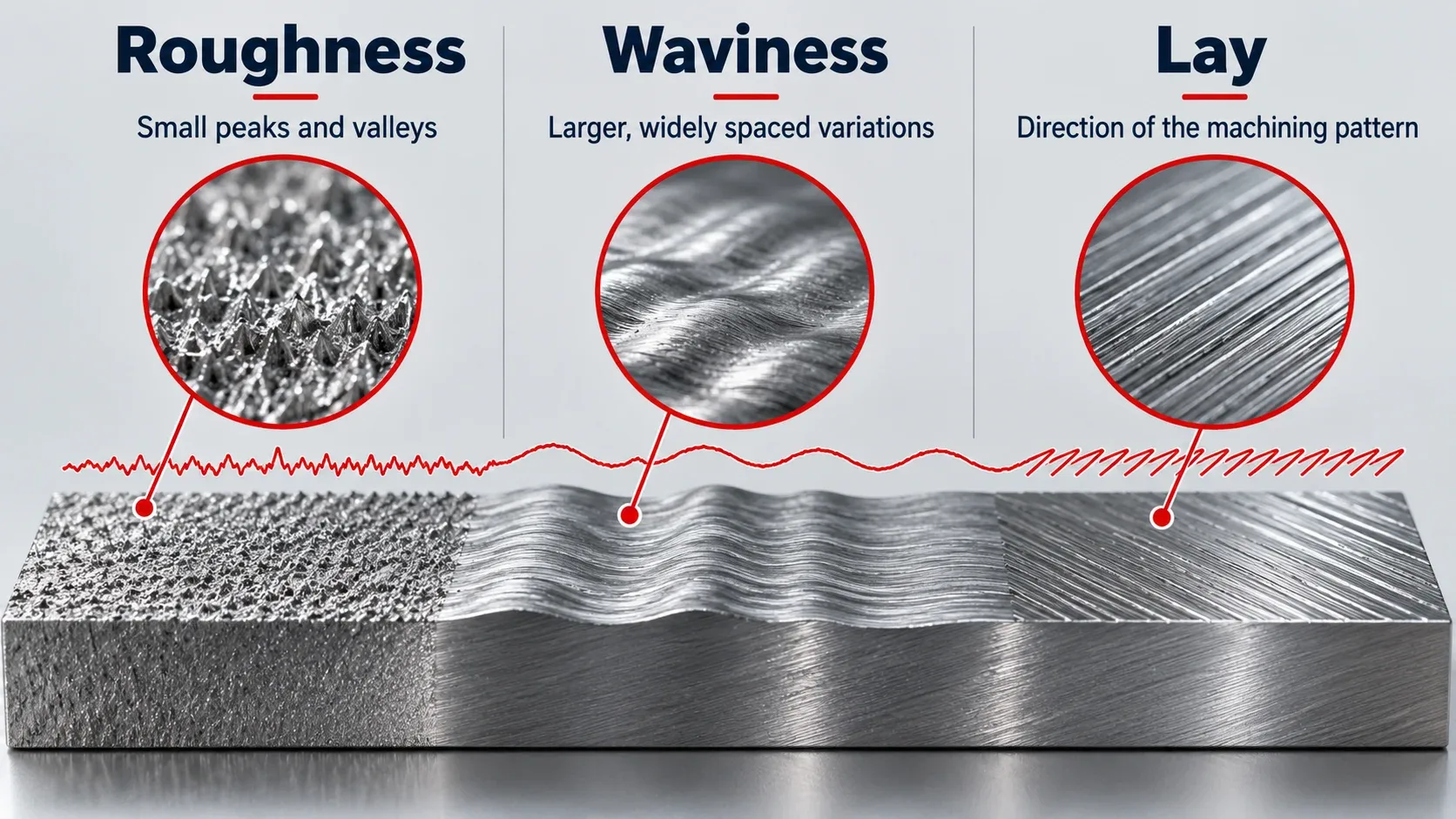
| Waviness | Larger and more widely spaced variations in the surface profile. |
| Lay | The dominant direction of the surface pattern or machining marks. |
Roughness, Waviness and Lay Explained
Surface Roughness
Roughness consists of small peaks and valleys that appear on a manufactured surface. These irregularities may result from cutting-tool geometry, feed marks, abrasive particles, machining conditions, or finishing operations.
Waviness
Waviness consists of larger surface variations with greater spacing than roughness. It can be caused by vibration, machine deflection, thermal distortion, chatter, or an unstable manufacturing process.
Lay
Lay describes the direction of the dominant surface pattern. A turned shaft often has circular or helical tool marks, while a milled surface may show parallel or crossed machining patterns.
Why Is Surface Finish Important?
Surface finish is not simply a cosmetic specification. It can influence several important mechanical and manufacturing properties.
Friction
Surface texture affects how two components slide or rotate against each other.
Wear
Excessively rough surfaces can increase contact stress and accelerate wear.
Sealing
Hydraulic, pneumatic, and gasket sealing surfaces often require controlled roughness.
Lubrication
Some controlled surface textures help retain lubricant between moving components.
Fatigue Life
Deep scratches or severe surface irregularities can act as stress concentration points.
Appearance
Polished and visible components may require a specific finish for aesthetic reasons.
Surface Finish Symbols on Engineering Drawings
Engineering drawings use standardized surface-texture symbols to communicate the required condition of a surface to machinists, manufacturers, and inspectors.
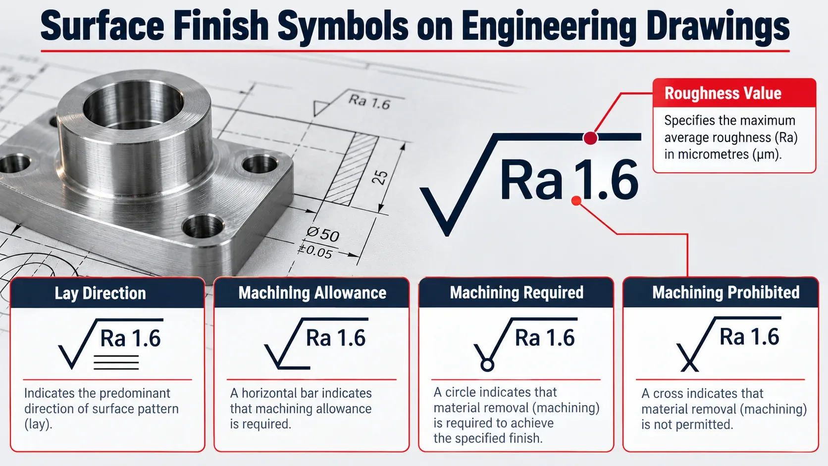
A surface finish callout may contain information about:
- Required surface roughness
- Whether material removal is required
- Whether machining is prohibited
- Manufacturing method
- Machining allowance
- Direction of lay
- Specified roughness parameter
How to Read a Surface Finish Callout
A common drawing requirement may appear as:
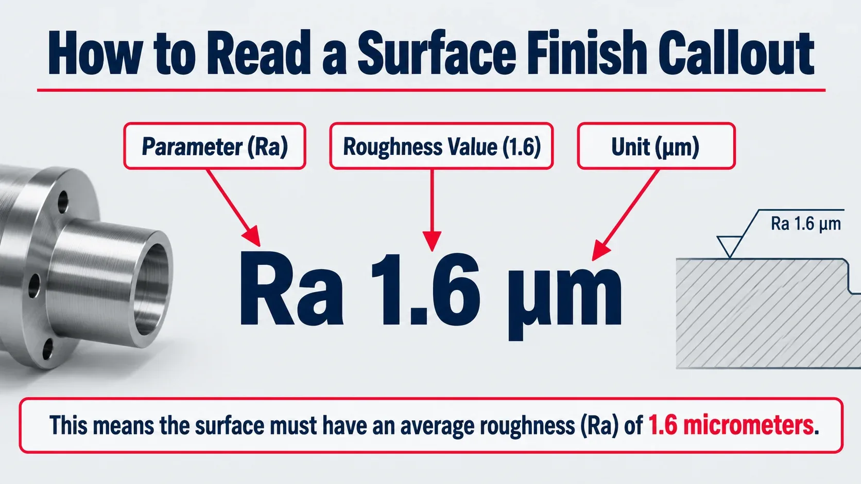
This callout can be interpreted as follows:
- Ra identifies the roughness parameter.
- 1.6 is the specified roughness value.
- μm means micrometers.
Additional information may be shown with the symbol to specify the manufacturing method, lay direction, machining allowance, or other surface requirements.
What Does Ra Surface Finish Mean?
Ra is one of the most commonly used surface roughness parameters. It represents the arithmetic average of the absolute deviations of a measured surface profile from its mean line over a specified evaluation length.
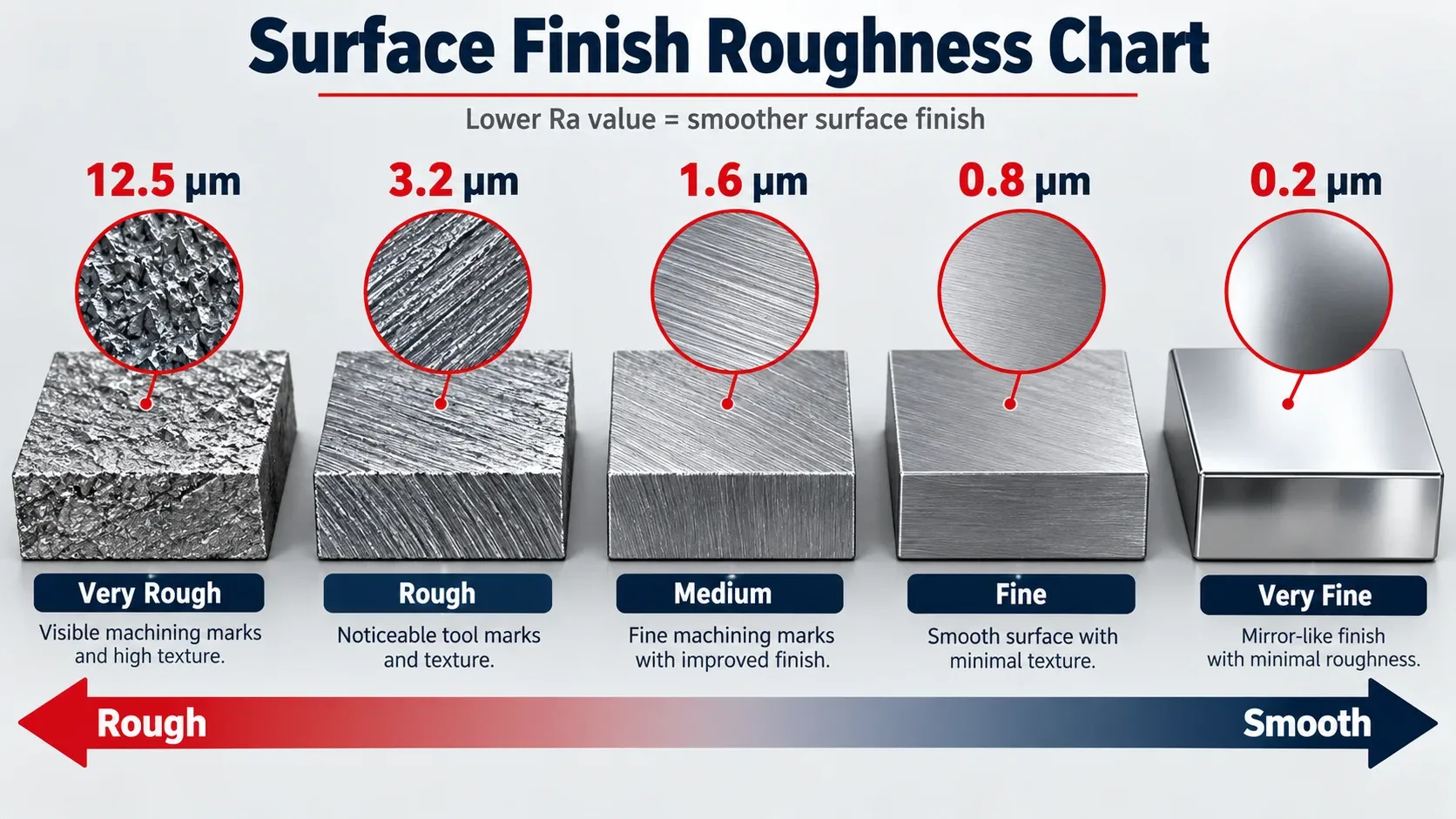
In practical terms, a lower Ra value generally indicates a smoother measured surface, while a higher value indicates a rougher surface.
| Example Ra Value | General Description |
|---|---|
| Ra 12.5 μm | Relatively rough machined surface |
| Ra 3.2 μm | Common machined finish |
| Ra 1.6 μm | Fine machined finish |
| Ra 0.8 μm | Fine precision finish |
| Ra 0.2 μm | Very smooth precision surface |
Ra vs Rz vs Rq vs Rt
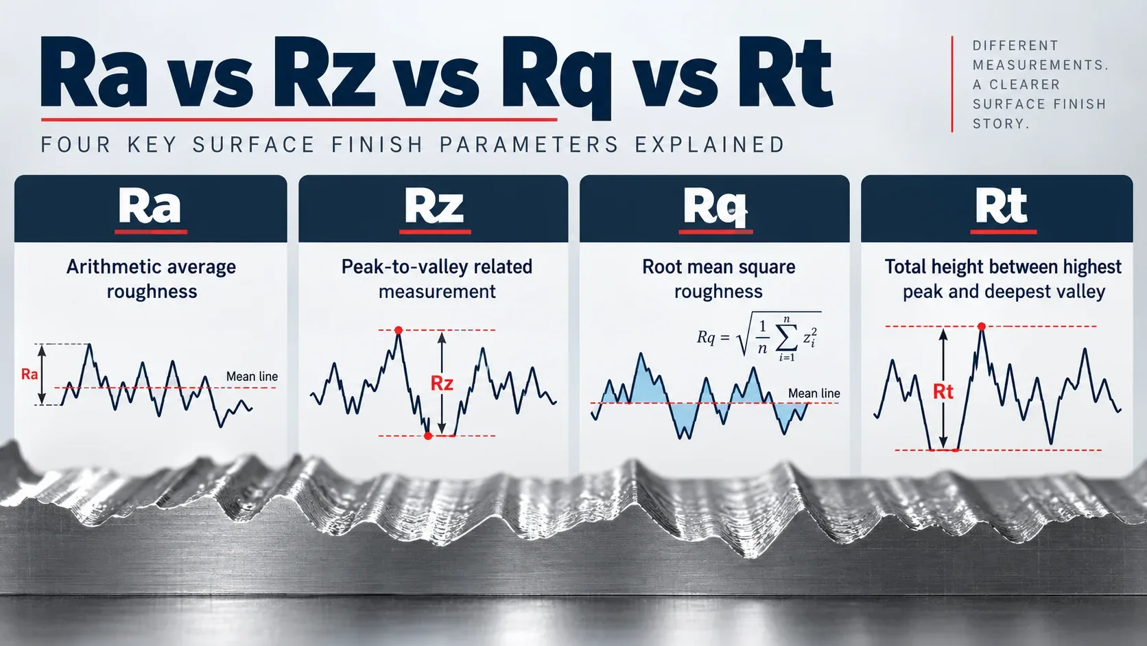
Ra is widely used, but it is not the only parameter used to evaluate surface roughness.
| Parameter | What It Represents | Typical Purpose |
|---|---|---|
| Ra | Arithmetic average roughness | General surface-quality specification |
| Rz | Peak-to-valley related surface-height measurement | Evaluating pronounced surface irregularities |
| Rq | Root mean square roughness | Detailed statistical evaluation of profile deviations |
| Rt | Total height between the highest peak and deepest valley | Identifying extreme profile variation |
Surface Finish Units: Micrometers vs Microinches
Surface roughness is commonly expressed in either micrometers (μm) or microinches (μin).
| Micrometers | Approx. Microinches |
|---|---|
| 0.2 μm | 8 μin |
| 0.4 μm | 16 μin |
| 0.8 μm | 32 μin |
| 1.6 μm | 63 μin |
| 3.2 μm | 126 μin |
| 6.3 μm | 248 μin |
| 12.5 μm | 492 μin |
Surface Finish Roughness Chart
The following chart provides a visual comparison of common Ra values from relatively rough surfaces to very smooth precision finishes.
| Ra μm | Approx. μin | General Finish | Possible Process |
|---|---|---|---|
| 25 | 984 | Very rough | Rough cutting or heavy machining |
| 12.5 | 492 | Rough machined | Rough turning or milling |
| 6.3 | 248 | Machined | General milling or turning |
| 3.2 | 126 | Standard machined | Controlled turning or milling |
| 1.6 | 63 | Fine machined | Finish turning or precision machining |
| 0.8 | 32 | Fine precision | Grinding or fine finishing |
| 0.4 | 16 | Very fine | Precision grinding or honing |
| 0.2 | 8 | Very smooth | Honing, lapping or fine polishing |
Typical Surface Finish by Manufacturing Process
Different production methods naturally create different surface textures. However, no process produces one fixed roughness value in every application.
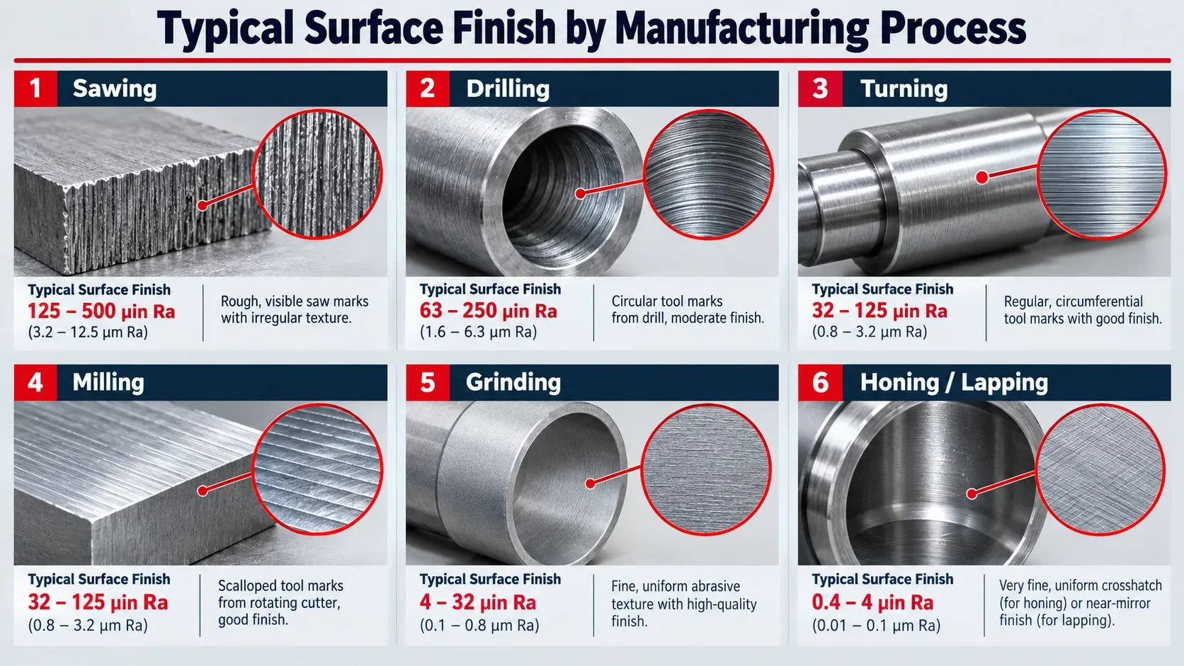
Sawing
Generally leaves a relatively rough surface with visible cutting marks.
Drilling
Surface quality depends strongly on drill condition, material, feed, and cutting speed.
Turning
Can produce anything from rough cuts to fine finishes depending on feed rate and tool geometry.
Milling
Creates directional cutter marks whose spacing depends largely on feed and cutter geometry.
Grinding
Commonly used when tighter dimensional accuracy and smoother surface finish are required.
Honing and Lapping
Often used for precision surfaces requiring very low roughness and controlled geometry.
Factors That Affect Surface Finish
The final surface finish depends on the complete machining system rather than a single setting.
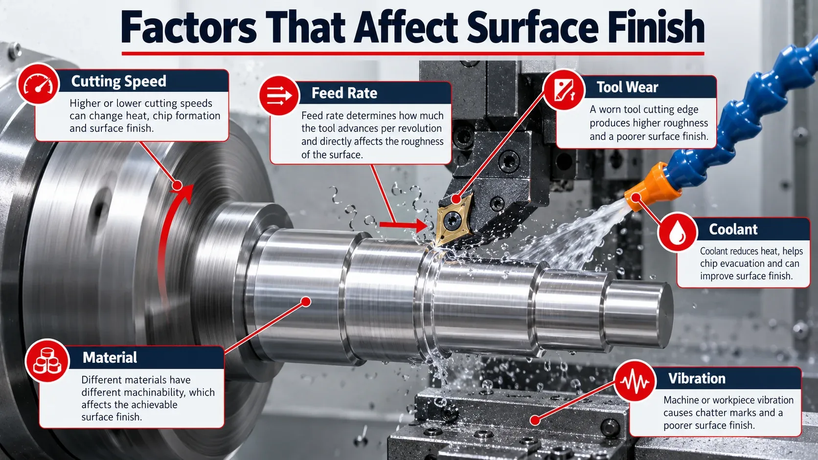
- Cutting speed: Incorrect speed can contribute to built-up edge, heat, or poor cutting action.
- Feed rate: Higher feed rates often leave more pronounced feed marks.
- Depth of cut: Heavy cuts can increase cutting forces and vibration.
- Tool geometry: Nose radius, rake angle, edge preparation, and cutter geometry influence texture.
- Tool wear: Worn or damaged cutting edges can significantly degrade surface quality.
- Machine rigidity: A flexible setup may produce vibration or chatter.
- Workpiece material: Materials respond differently to machining and finishing operations.
- Coolant and lubrication: Proper fluid application can improve cutting conditions and tool life.
- Runout: Excessive spindle, tool, or workpiece runout can create inconsistent texture.
- Vibration: Chatter frequently creates visible and measurable surface waviness.
How Is Surface Finish Measured?
Surface finish can be evaluated using contact instruments, optical systems, or physical comparison methods.
Contact Measurement
A stylus-based instrument physically moves across the surface and records changes in height.
Non-Contact Measurement
Optical systems can evaluate a surface without physically touching it.
Comparator Method
A surface roughness comparator allows a machinist or inspector to compare a part against reference specimens.
Measuring Surface Roughness With a Profilometer
A stylus profilometer is one of the most familiar instruments used for measuring surface roughness.
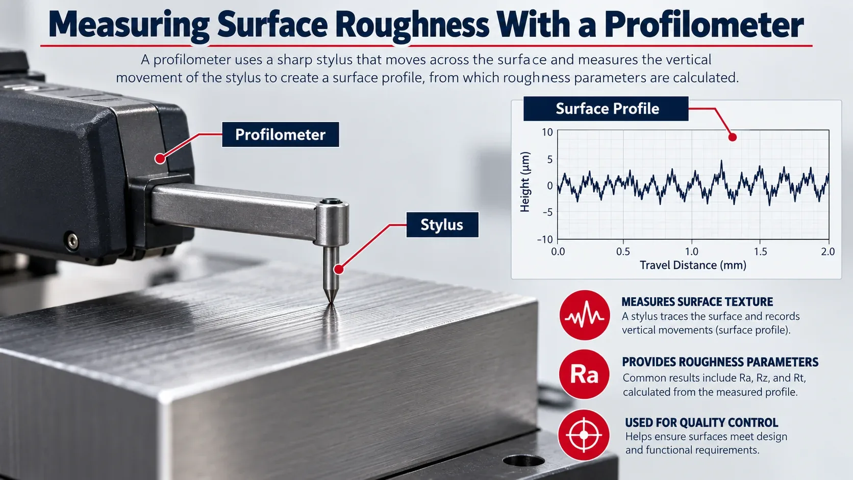
- A fine stylus is positioned on the surface.
- The instrument moves the stylus across a specified evaluation path.
- The stylus follows microscopic peaks and valleys.
- The vertical movement is converted into an electrical signal.
- Software processes the profile and calculates parameters such as Ra, Rz, or Rt.
Measurement accuracy can depend on stylus direction, cutoff length, evaluation length, filtration, surface cleanliness, and instrument setup.
Non-Contact Surface Finish Measurement
Advanced surface inspection can also be performed using non-contact technologies.
- Optical profilometry
- Confocal microscopy
- Interferometry
- Laser-based surface scanning
Example: Reading Surface Finish on an Engineering Drawing
Consider a precision shaft where the bearing seat is specified as:
This means the designated bearing surface must meet the specified Ra roughness requirement.
A relatively fine finish may be required because the shaft must operate inside a bearing where friction, lubrication, fit, and wear are important.
How to Choose the Correct Surface Finish
The lowest possible roughness value is not automatically the best choice. Surface finish should be selected according to the actual function of the component.
- Friction requirements
- Lubrication retention
- Sealing performance
- Wear resistance
- Fatigue performance
- Required fit
- Coating or plating requirements
- Manufacturing capability
- Inspection capability
- Production cost
Why Tighter Surface Finish Requirements Cost More
Producing a very smooth surface usually requires greater manufacturing control and may require additional operations.
- Slower machining speeds or feed rates
- More precise cutting tools
- Additional grinding
- Honing or lapping
- Special polishing operations
- More frequent tool replacement
- Additional inspection
- Greater rejection risk
Common Surface Finish Mistakes
- Assuming Ra and Rz mean the same thing
- Believing that the lowest Ra value is always best
- Ignoring the direction in which roughness is measured
- Confusing dimensional tolerance with surface finish
- Assuming one machining process always produces the same Ra value
- Inspecting contaminated, oily, or damaged surfaces
- Ignoring cutoff and evaluation conditions
- Failing to check which engineering standard applies
Surface Finish Standards
Surface texture terminology, drawing symbols, measurement methods, and parameter definitions are covered by recognized engineering standards.
Standards that may be relevant include the ISO 21920 series for profile surface texture, drawing-related references associated with ISO 1302, and standards such as ASME Y14.36.
Surface Finish Quick Reference
Surface finish: Overall condition and texture of a manufactured surface.
Ra: Arithmetic average surface roughness.
Rz: Height-related roughness parameter.
Rq: Root mean square roughness.
Rt: Total profile height.
μm: Micrometer.
μin: Microinch.
Frequently Asked Questions About Surface Finish
What does surface finish mean?
Surface finish describes the texture and condition of a manufactured surface, including characteristics such as roughness, waviness, and lay.
What is a good surface finish?
There is no single surface finish that is best for every component. The correct finish depends on the function of the surface.
Is Ra 1.6 μm a smooth surface finish?
Ra 1.6 μm is generally considered a relatively fine machined finish.
What is the difference between Ra and Rz?
Ra represents an arithmetic average of profile deviations, while Rz focuses more strongly on peak-to-valley characteristics.
Does a lower Ra number mean a smoother surface?
Generally, yes. A lower Ra value indicates smaller average profile deviations.
Key Takeaways About Surface Finish
Surface finish is an important engineering specification that describes the condition and texture of a manufactured surface.
Understanding surface finish requires more than simply looking at a roughness number. Engineers, machinists, and inspectors should consider roughness, waviness, lay, measurement direction, manufacturing process, component function, and the applicable engineering standard.
Ra is one of the most commonly used roughness parameters, while Rz, Rq, and Rt provide additional information about the surface profile.