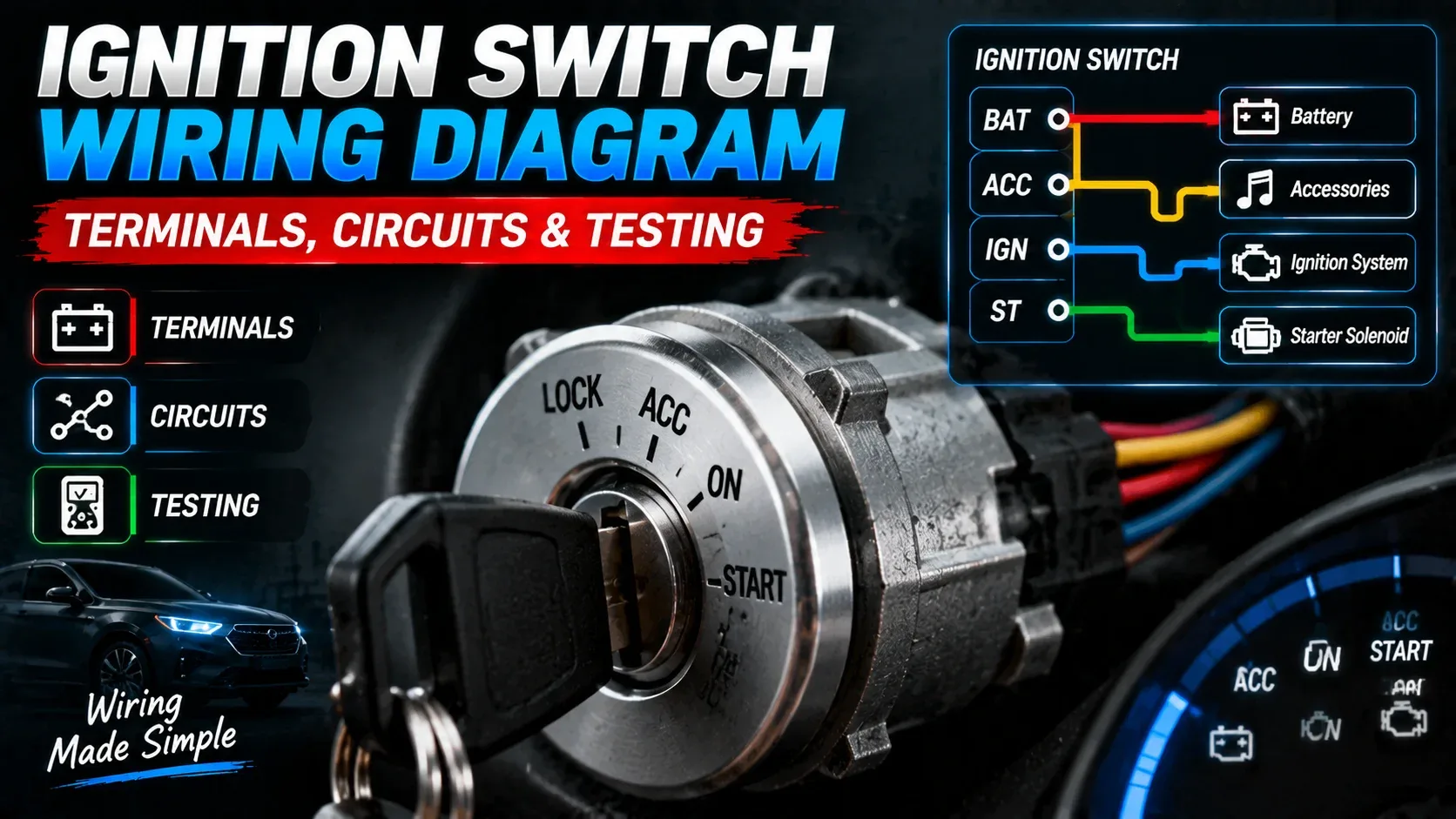

An ignition switch diagram is a map of battery power moving through ACC, IGN, and START circuits. Learn what the terminals do, which checks matter, and how to test before replacing parts.
What does an ignition switch do?
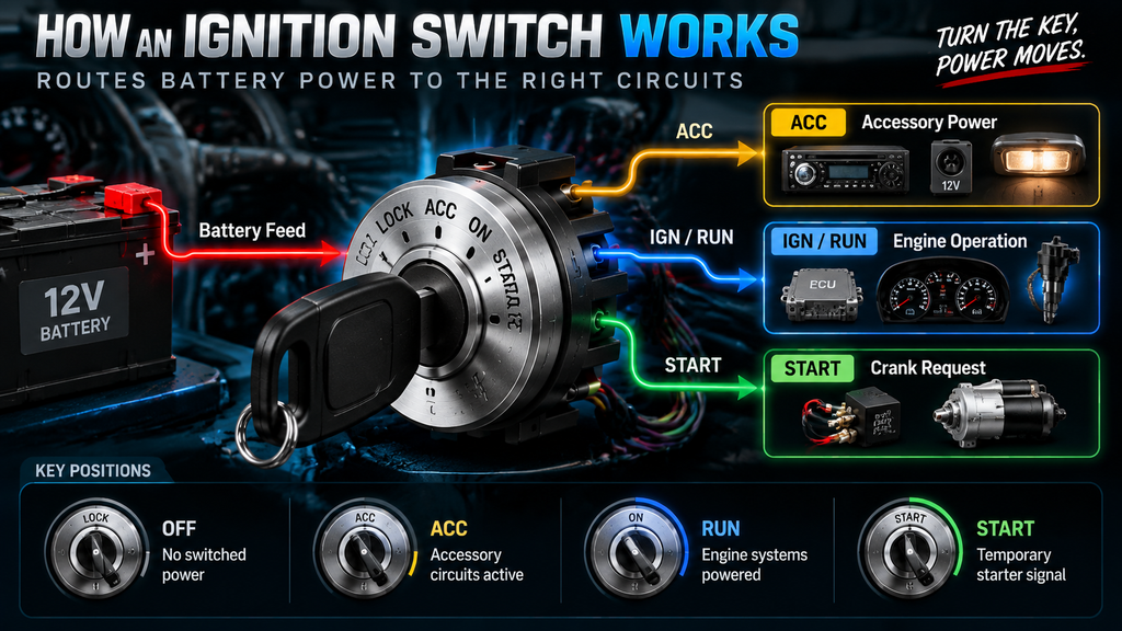
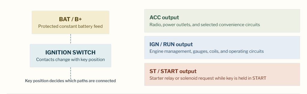
The ignition switch is a power-routing device. It receives a protected battery feed and, depending on key position, connects that feed to accessory, run, and start circuits. It is not the ignition coil, starter motor, or engine computer; it is the control point that tells those systems when power is allowed to flow.
In a typical keyed vehicle, OFF removes switched outputs, ACC powers selected convenience items, RUN powers the systems needed for normal operation, and START temporarily requests cranking through a relay or starter solenoid. Modern vehicles may add an immobilizer, body-control module, clutch switch, or park/neutral switch between the key and the starter.
Practical diagnostic note
If the radio and dash wake up but the engine will not crank, do not immediately blame the battery or replace the switch. First verify whether the START output receives voltage while the key is held in START, then check the starter relay, safety interlock, fuse, wiring, and ground path.
Follow power flow, not wire color
Most diagrams become easier once you read them in one direction: battery source, protection device, switch contact, output circuit, load, then ground. A line on the diagram represents an electrical path; labels and connector numbers identify the path more reliably than insulation color alone.
Ignition switch terminals explained
Abbreviations differ slightly between manufacturers and aftermarket switches, but these four labels describe the functions found in many ignition switch diagrams. Verify the terminal legend on the switch body and compare it with a vehicle-specific diagram before connecting anything.
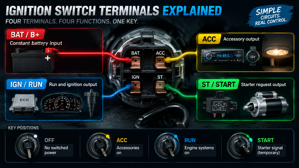
BAT / B+
Constant battery input
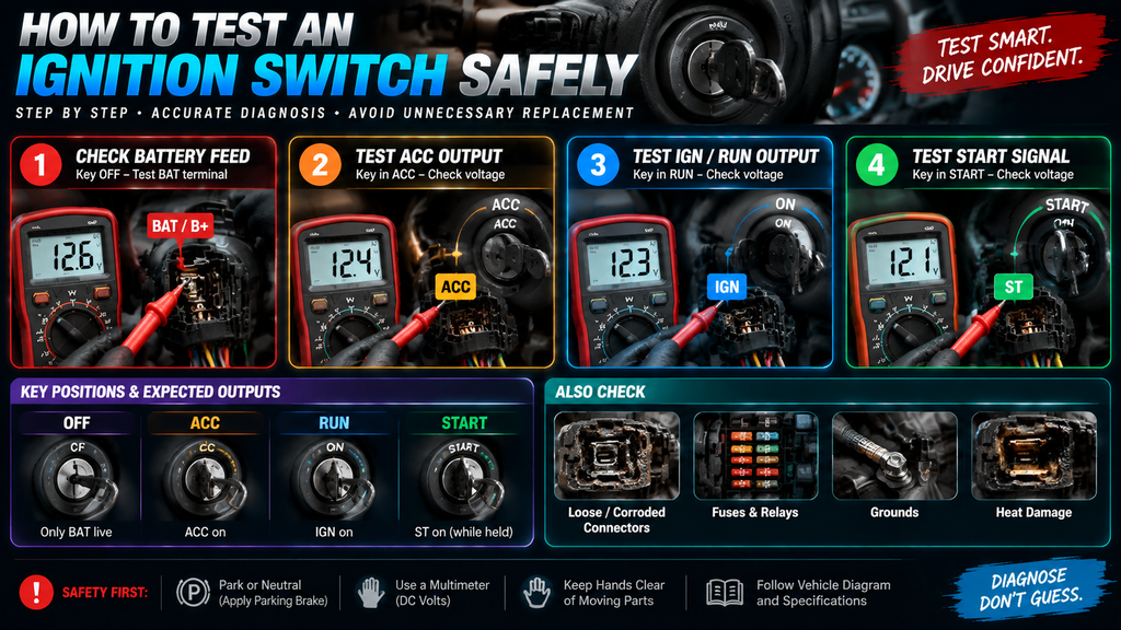
This is the incoming power supply, usually fed through a fuse or fusible link. It should have battery voltage even with the key OFF. Never assume the largest wire is BAT without testing and diagram confirmation.
ACC
Accessory output
ACC commonly powers items such as the radio, accessory socket, or blower-control feed without energizing every engine circuit. Some vehicles drop ACC during cranking to reduce electrical load.
IGN / RUN
Run and ignition output
The RUN output supplies circuits needed while the engine operates. Depending on the vehicle, this can include engine-control relays, ignition coils, instruments, charging-system warning lamps, and fuel-system control circuits.
ST / START
Starter request output
This output is active only while the key is held against spring pressure in START. It often triggers a relay rather than powering the starter motor directly. A no-crank fault can exist anywhere after this terminal.
Identify wires by function, then prove them
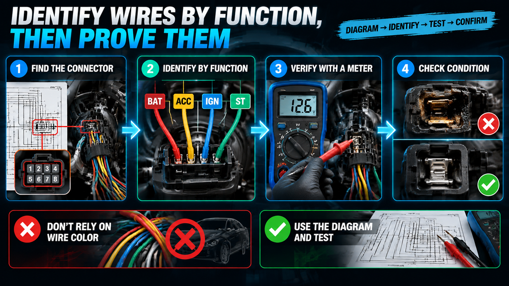
A basic ignition switch may have one battery feed, one ACC wire, one or more IGN/RUN wires, and a START wire. Factory systems can be more complex: separate ignition feeds may remain live in different key positions, and the start request may travel through a body-control module or an anti-theft system before it reaches a starter relay.
The safe process is to locate the connector in the factory diagram, identify terminal numbers, confirm the expected voltage in each key position, and inspect the connector for heat damage or loose pins. Do not use a generic online color chart as proof. A correct color on one model can be a different circuit on another.
How to test an ignition switch safely
Use a digital multimeter set to DC volts and a known good chassis ground or battery negative terminal. Back-probe only when the connector design allows it; forcing probes into terminals can spread contacts and create a new intermittent fault. Keep the vehicle secured in Park or Neutral with the parking brake applied.
Confirm the battery feed first
With the key OFF, measure voltage between the specified BAT terminal and ground. A healthy charged 12-volt battery is commonly near 12.6 volts at rest, but always interpret the reading alongside battery condition and the manufacturer’s specifications. No power here points upstream to a fuse, fusible link, connector, or battery cable issue.
Check ACC and RUN outputs
Turn the key to ACC and test the expected accessory output. Then move it to RUN and test the IGN/RUN output or outputs identified by the wiring diagram. The correct test is not simply whether voltage appears; it is whether it appears on the correct terminal in the correct key position.
Test the START request
Hold the key in START and watch the ST terminal. It should receive voltage only during the crank request. Use an assistant if needed and keep hands, leads, clothing, and tools away from moving engine components. If voltage is present at ST but the engine does not crank, follow the circuit downstream.
Separate switch failure from voltage-drop faults
A terminal can show voltage with no load but fail when current demand rises because of burnt contacts, corrosion, or damaged wiring. If symptoms are intermittent, inspect connector tension, heat discoloration, fuse-box terminals, grounds, and relay operation. A loaded voltage-drop test may be needed for a confident diagnosis.
| Key position | Expected switched output | What the result suggests |
|---|---|---|
| OFF | BAT feed remains live; ACC, IGN, and ST are normally off. | Switched output in OFF can indicate a stuck switch contact, retained-power design, or a different circuit than expected. |
| ACC | ACC circuit active; IGN may remain off depending on design. | No ACC voltage with a healthy BAT feed can point to the switch, connector, or an upstream protection issue. |
| RUN / ON | IGN/RUN circuits active; ACC may also be active. | Missing RUN output can explain a dead dash, no engine-control power, or an engine that starts briefly then stalls. |
| START | ST active only while key is held; some accessories may drop out. | If ST is correct, check interlocks, relay control, starter wiring, grounds, and the starter itself before condemning the switch. |
Common ignition switch wiring problems
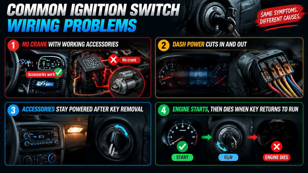
Ignition-switch symptoms overlap with battery, relay, fuse, starter, sensor, and security-system faults. Use the symptom to choose the next test point rather than using it as proof that one part has failed.
No crank with working accessories
Check ST output during START. If it is missing, inspect the switch feed, switch contacts, connector, and key-cylinder actuator. If it is present, test the park/neutral or clutch switch, starter relay, starter circuit, and battery cable voltage drop.
Dash power cuts in and out
A worn switch contact, loose connector, damaged actuator, or overheated terminal can interrupt RUN power. Look for heat marks, a loose-feeling key position, changes when the key is gently moved, and voltage loss at the affected IGN output.
Accessories stay powered after key removal
Some vehicles deliberately retain accessory power until a door opens, so verify normal operation first. If power never times out, investigate the ignition switch, retained-accessory-power relay or module, and any aftermarket stereo or remote-start wiring.
Engine starts, then dies when key returns to RUN
This pattern can happen when a start-only feed works but the RUN ignition feed does not. Confirm RUN voltage after releasing the key, then consider immobilizer, fuel, engine-control, and ignition-system faults identified by the vehicle’s diagnostic information.
Ignition switch wiring FAQs
What wires go to an ignition switch?
Common functions include a constant battery feed (BAT or B+), an accessory output (ACC), one or more ignition/run outputs (IGN), and a start request output (ST). The number of wires and exact terminal names vary by vehicle, so use the correct wiring diagram and test terminal function before making a connection.
What does ACC mean on an ignition switch?
ACC means accessory. It usually powers selected convenience circuits, such as audio or power outlets, without placing the entire engine-control system in RUN mode. The exact list of powered circuits differs between vehicles.
How do I know whether my ignition switch is bad?
Confirm a good BAT feed, then check whether the switch produces the specified ACC, RUN, and START outputs in the correct key positions. A missing or unstable output with a healthy input supports a switch or connector fault, but downstream relays, safety switches, and modules must still be ruled out.
Can I bypass an ignition switch?
Do not bypass it as a repair method. Jumping ignition circuits can cause shorts, starter engagement, airbag-system damage, theft-deterrent issues, or vehicle movement. Diagnose the actual fault with the correct diagram and repair the failed switch, actuator, connector, fuse, relay, or wiring.
Are ignition switch wires universal?
No. Function labels are often similar, but wire colors, pin locations, circuit protection, and module involvement vary widely by manufacturer and model year. Treat generic diagrams as learning tools only and use a factory or reputable vehicle-specific wiring diagram for repairs.