
Milling is one of the most widely used machining processes in modern manufacturing. It uses a rotating cutting tool to remove material from a workpiece and create accurate surfaces, slots, pockets, contours, and other features.
Milling is a subtractive machining process in which a rotating multi-point cutting tool removes material from a workpiece. Controlled movement between the cutter and workpiece produces the required shape, size, and surface.
What Is Milling?
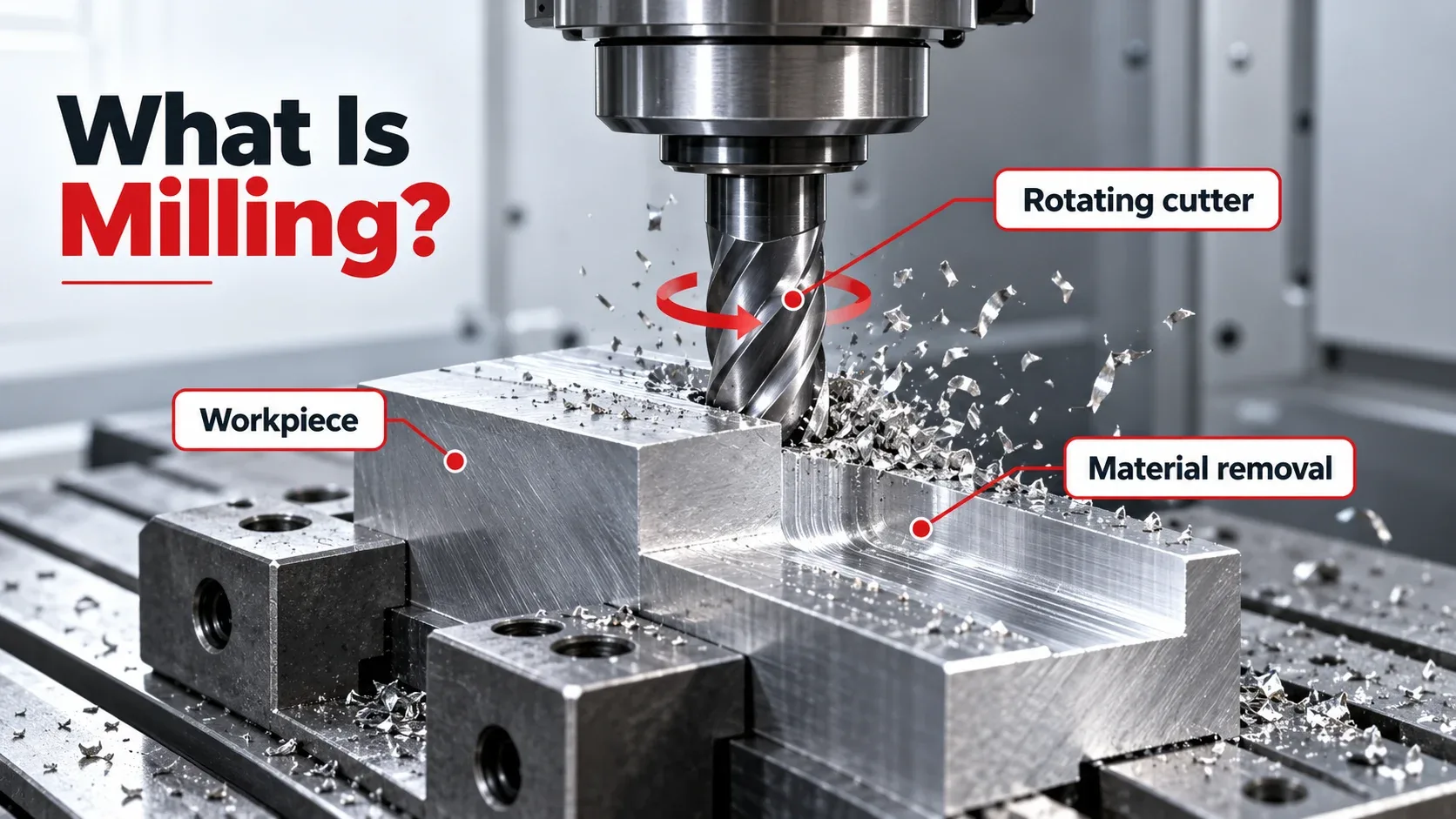
A simple milling definition is the controlled removal of material from a workpiece using a rotating cutting tool. Milling is considered a subtractive manufacturing process because material is removed rather than added.
The milling meaning in machining refers to a process in which multiple cutting edges repeatedly contact a workpiece and remove small chips. This allows manufacturers to create accurate flat surfaces, grooves, slots, pockets, profiles, and complex three-dimensional forms.
Milling is a machining process that uses a rotating multi-point cutter to remove unwanted material from a workpiece and produce specific dimensions, shapes, and surface features.
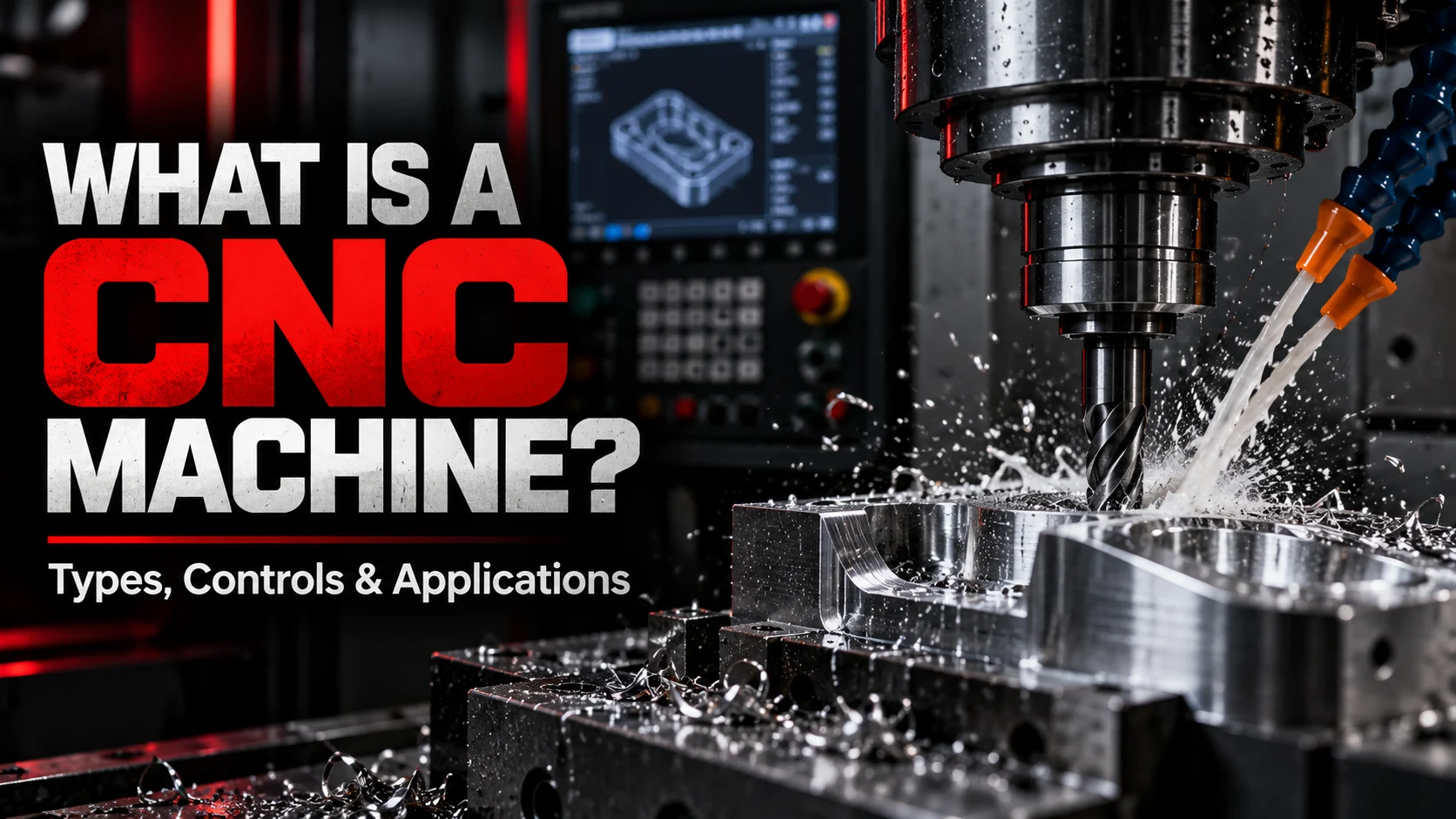
Milling can be performed using conventional manually operated machines or computer numerical control equipment. CNC milling allows complex toolpaths and repeatable machining operations to be carried out automatically.
How Does Milling Work?
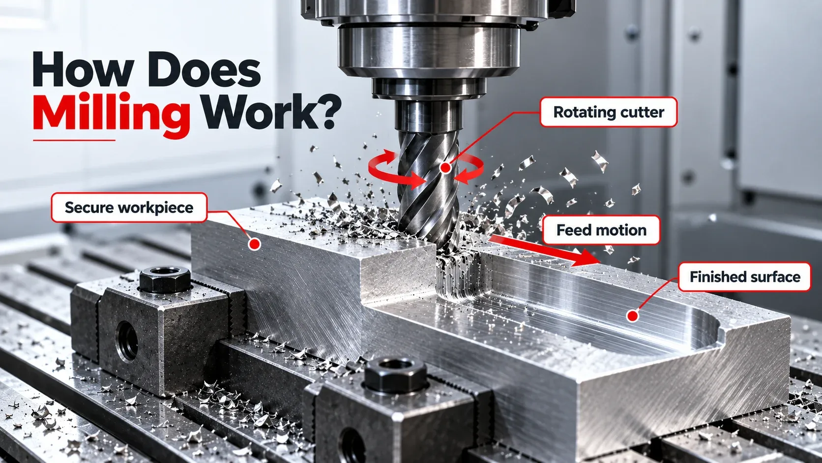
Milling works by creating controlled movement between a rotating cutting tool and a securely held workpiece. As each cutting edge passes through the material, it removes a small chip.
-
Secure the workpiece.
The material is fixed in a vise, fixture, clamps, or another suitable workholding system. -
Select the milling cutter.
The cutter is chosen according to the workpiece material and required feature. -
Mount the tool.
The milling cutter is mounted securely in the machine spindle. -
Set cutting parameters.
Spindle speed, feed rate, depth of cut, and other settings are selected. -
Start material removal.
The rotating tool enters the workpiece while controlled movement produces the required cut. -
Complete finishing passes.
Additional passes may be performed to achieve the final dimensions and surface finish.
Main Parts of a Milling Machine
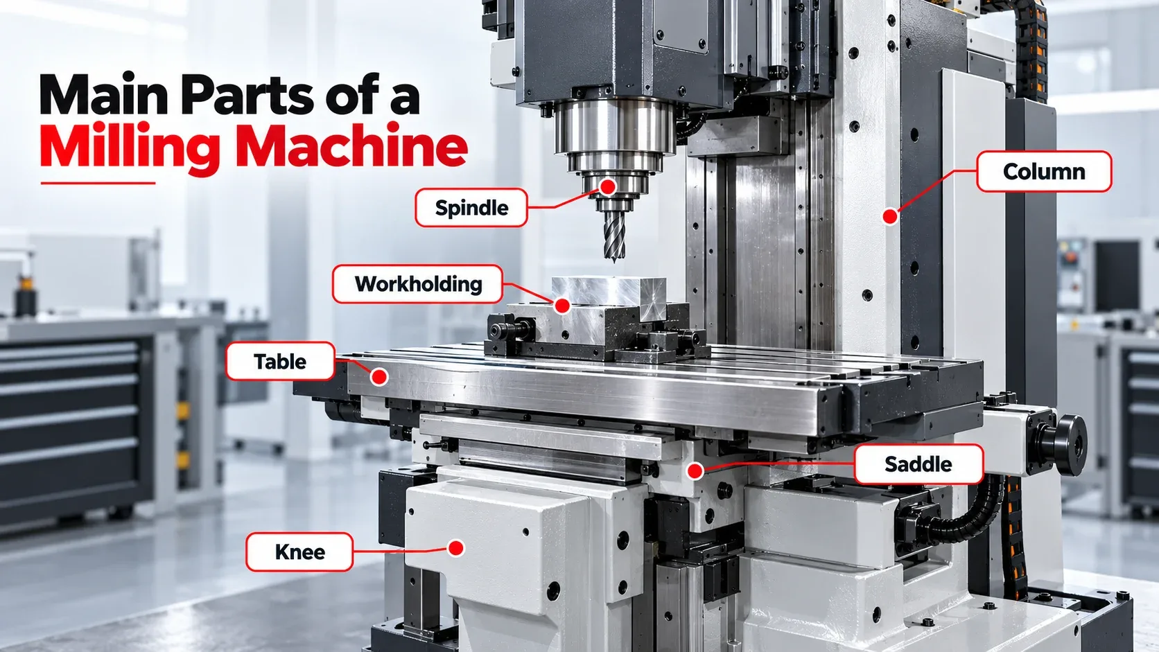
Spindle
The spindle holds and rotates the milling cutter during machining.
Table
The machine table supports the vise, fixture, and workpiece.
Column
The column provides structural support for major machine components.
Knee & Saddle
These components support and position the table on many conventional mills.
Cutting Tool
The cutter contains sharp edges that remove material from the workpiece.
Workholding System
Vises, fixtures, and clamps prevent workpiece movement during cutting.
Types of Milling Machines
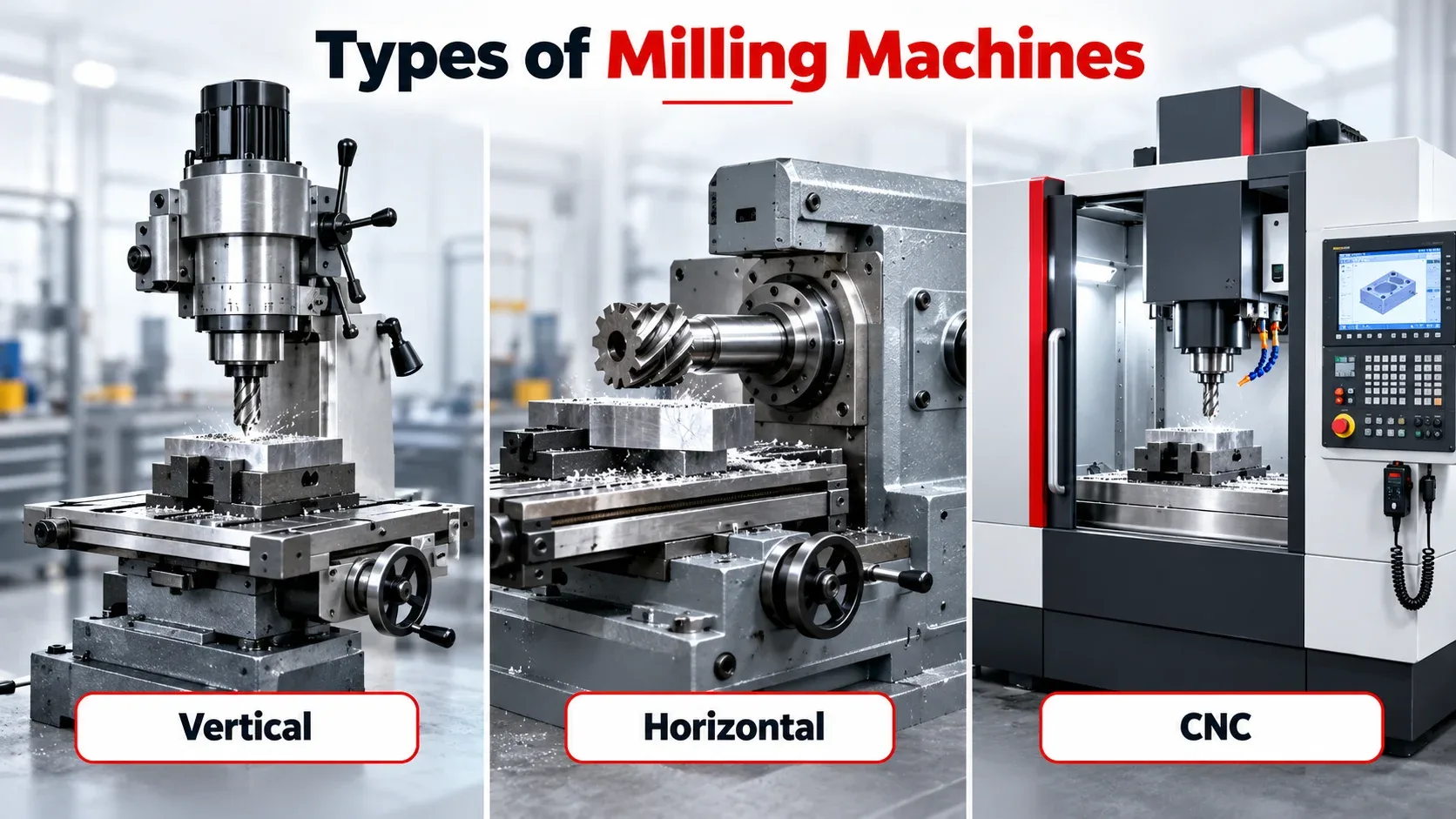
Vertical Milling Machine
A vertical mill has a vertically positioned spindle and is commonly used for end milling, face milling, drilling, pocketing, and general machining.
Horizontal Milling Machine
A horizontal mill positions the spindle horizontally and is often suitable for heavy cuts, grooves, side milling, and larger workpieces.
CNC Milling Machine
CNC milling machines use programmed instructions to control the machine axes, spindle, feeds, and toolpaths.
Universal Milling Machine
Universal milling machines provide additional positioning flexibility for a wide variety of machining operations.
Bed-Type Milling Machine
Bed-type milling machines use rigid construction suitable for heavier machining and larger components.
Machining Center
A CNC machining center can combine milling, drilling, tapping, boring, and automatic tool changes.
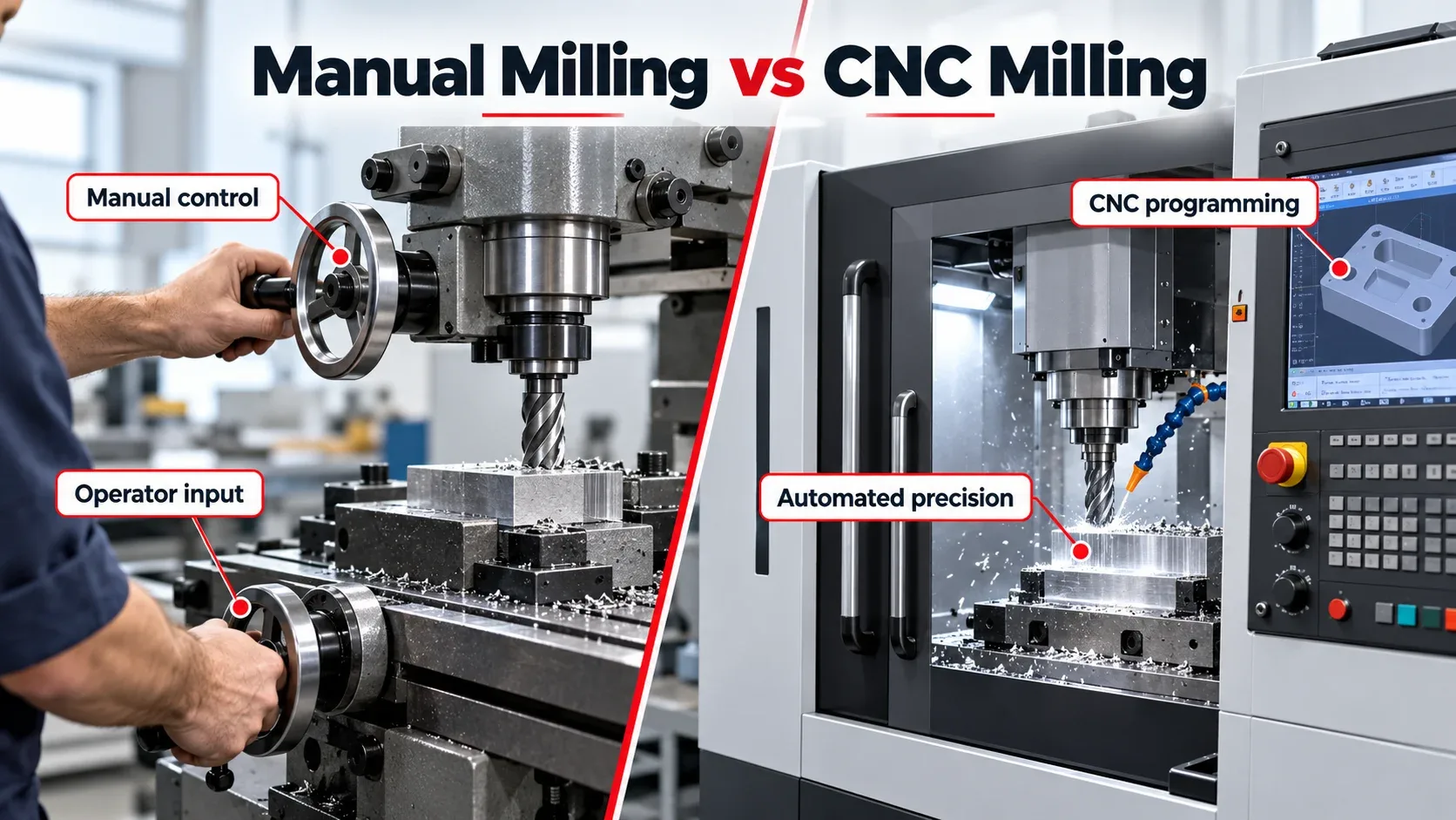
Manual Milling vs CNC Milling
| Feature | Manual Milling | CNC Milling |
|---|---|---|
| Control | Operator controlled | Computer controlled |
| Repeatability | Depends heavily on operator skill | High repeatability |
| Complex Shapes | More difficult | Easier with programmed toolpaths |
| Programming | Usually not required | Required |
| Automation | Limited | High |
| Typical Use | Repairs, prototypes, one-off work | Complex parts and production machining |
Common Types of Milling Operations
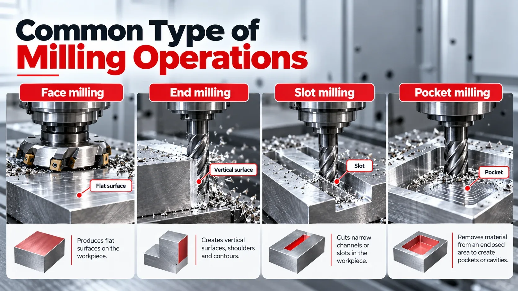
Face Milling
Face milling is primarily used to create broad, flat surfaces.
Peripheral Milling
Peripheral milling uses cutting edges around the outer circumference of the cutter.
End Milling
End mills are used for slots, pockets, profiles, and general-purpose cutting.
Slot Milling
Slot milling produces straight or shaped channels in the workpiece.
Side Milling
Side milling removes material from the sides of a workpiece.
Angular Milling
Angular milling creates surfaces at specific angles.
Profile Milling
Profile milling follows an internal or external contour.
Pocket Milling
Pocket milling removes material from an enclosed region of the workpiece.
Form Milling
Form milling uses specially shaped cutters to create curved or irregular surfaces.
Gang Milling
Gang milling uses multiple cutters simultaneously to machine several surfaces.
Climb Milling vs Conventional Milling
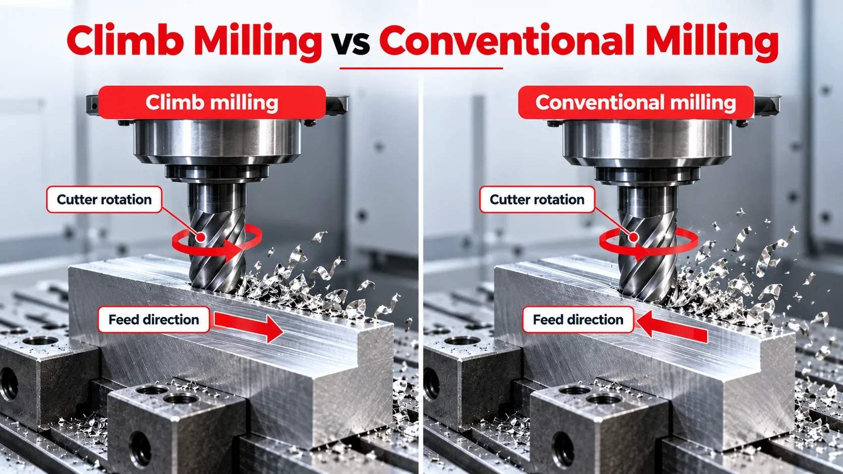
Climb Milling
In climb milling, cutter rotation moves in the same general direction as the feed at the point of cutting.
The chip typically starts thicker and becomes thinner as the cutting edge exits.
Conventional Milling
In conventional milling, cutter rotation opposes the workpiece feed direction.
The chip generally starts thin and becomes thicker as cutting progresses.
Common Milling Cutters
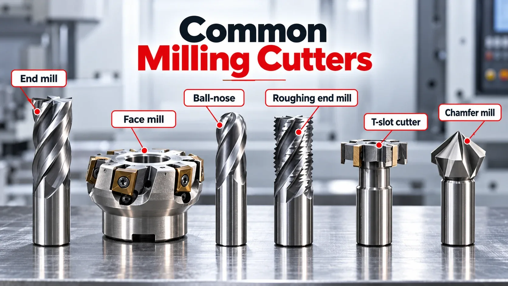
End Mill
Used for slots, pockets, contours, and side cutting.
Face Mill
Designed to machine large flat surfaces efficiently.
Ball-Nose End Mill
Commonly used for curved surfaces and 3D contours.
Roughing End Mill
Designed to remove larger amounts of material during rough machining.
Slitting Saw
Used for narrow slots and cut-off operations.
T-Slot Cutter
Designed for machining T-shaped slots.
Chamfer Mill
Used for chamfers, deburring, and countersinking.
Shell Mill
Commonly used for larger surfaces and heavier cuts.
Thread Mill
Creates internal or external threads using a programmed CNC toolpath.
What Materials Can Be Milled?
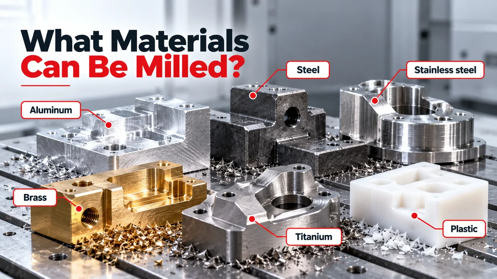
Milling can be used on many engineering materials, but the correct cutter, speeds, feeds, and machining strategy depend on the specific material.
Aluminum
Widely machined because many grades cut efficiently.
Steel
Requires suitable tooling and controlled cutting parameters.
Stainless Steel
Requires careful control of heat and tool engagement.
Cast Iron
Machinable but may produce abrasive chips and dust.
Brass & Copper
Tool geometry should be selected according to the specific alloy.
Titanium
Requires rigid setups and careful heat management.
Engineering Plastics
Require attention to heat buildup and chip evacuation.
Composite Materials
May require specialized tooling and dust-control methods.
Wood
Can also be milled with suitable machinery, tooling, and cutting parameters.
Important Milling Parameters
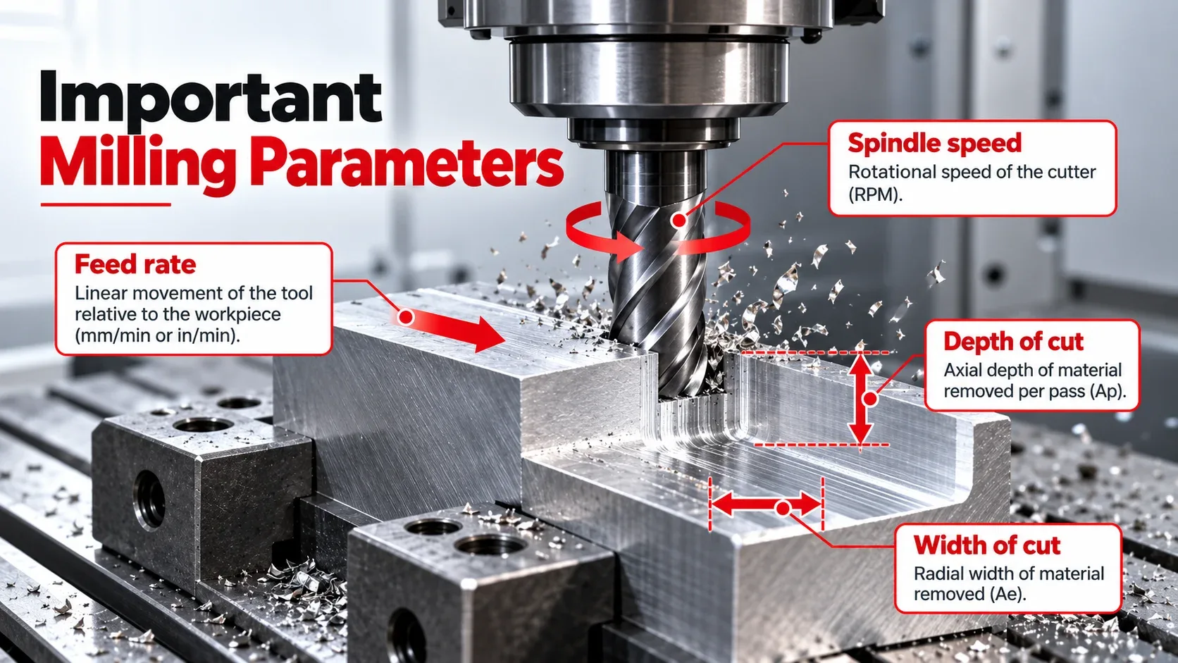
Spindle Speed
Spindle speed describes how quickly the cutter rotates, usually in RPM.
Feed Rate
Feed rate describes how quickly the cutting tool moves through the material.
Depth of Cut
Depth of cut determines how deeply the tool enters the workpiece in one pass.
Width of Cut
Width of cut refers to how much of the cutter engages the workpiece laterally.
Tool Geometry
Cutter diameter, flute count, helix angle, coating, and cutting-edge geometry affect machining performance.
Coolant & Lubrication
Coolant, air, or lubrication may be used to manage chips, heat, and tool life.
Milling Process: Step by Step
- Review the engineering drawing or CAD model.
- Select the correct workpiece material.
- Choose a suitable milling machine.
- Select the required cutting tools.
- Secure the workpiece properly.
- Establish machine and work reference positions.
- Set spindle speed, feed rate, and cutting depth.
- Perform roughing passes.
- Complete finishing passes.
- Inspect the finished component.
Advantages and Limitations of Milling
Advantages
- Creates accurate and complex shapes.
- Works with many materials.
- Suitable for slots, pockets, contours, and flat surfaces.
- CNC milling provides excellent repeatability.
- Multiple operations can often be completed in one setup.
- Large variety of cutting tools available.
Limitations
- Machines and tooling can be expensive.
- Complex CNC work requires programming skills.
- Tools wear over time.
- Some parts require multiple setups.
- Chip and heat management are necessary.
- Tool access limits some internal features.
Applications of Milling
Automotive Manufacturing
Milling is used for engine components, housings, brackets, tooling, and precision automotive parts.
Aerospace
CNC milling produces structural parts, brackets, housings, and lightweight aerospace components.
Medical Manufacturing
Precision milling is used for specialized components, instruments, fixtures, and manufacturing tools.
Mold & Die Making
Milling produces complex cavities, contours, molds, dies, and tooling surfaces.
Industrial Machinery
Machine bases, brackets, plates, housings, and repair components are commonly milled.
Prototype Development
CNC milling allows engineers to create functional prototypes from production materials.
Milling vs Turning: What Is the Difference?
| Feature | Milling | Turning |
|---|---|---|
| Primary Rotation | Cutting tool rotates | Workpiece rotates |
| Machine | Milling machine or machining center | Lathe or turning center |
| Common Tool | Multi-point cutter | Typically a single-point turning tool |
| Typical Features | Slots, pockets, flats, profiles, contours | Cylindrical and rotational shapes |
| Typical Parts | Brackets, plates, housings, molds | Shafts, pins, bushings |
Basic Milling Safety
- Secure the workpiece and tool before starting the machine.
- Use machine guards and enclosure doors correctly.
- Never touch a rotating cutter.
- Keep loose clothing, jewelry, and hair away from moving parts.
- Wear suitable eye protection.
- Never remove sharp chips with bare hands.
- Stop the spindle before making manual adjustments when required.
- Follow manufacturer instructions and workplace safety procedures.
Frequently Asked Questions About Milling
What is milling in simple terms?
Milling is a machining process in which a rotating cutting tool removes material from a workpiece to create a required shape or surface.
What is the main purpose of milling?
Milling is used to produce accurate surfaces, slots, pockets, contours, profiles, and other machined features.
What does a milling machine do?
A milling machine controls the movement between a rotating cutter and workpiece so material can be removed accurately.
What is CNC milling?
CNC milling uses computer numerical control to automate machine movement, cutting paths, spindle operation, and other functions.
What is the difference between milling and drilling?
Drilling is mainly used to create round holes, while milling can produce flat surfaces, slots, pockets, contours, profiles, and many other features.
What are the main types of milling?
Common types include face milling, end milling, peripheral milling, slot milling, profile milling, pocket milling, form milling, and angular milling.
What materials can be milled?
Common materials include aluminum, steel, stainless steel, cast iron, brass, copper, titanium, plastics, composites, and some types of wood.
Is milling the same as machining?
No. Milling is one type of machining. Other machining processes include turning, drilling, grinding, boring, and broaching.
What is the difference between a milling machine and a lathe?
In milling, the cutting tool primarily rotates. In turning, the workpiece primarily rotates while the cutting tool removes material.
Final Thoughts on Milling
Milling is a versatile machining process that uses a rotating multi-point cutting tool to remove material from a workpiece. It can create flat surfaces, slots, pockets, profiles, contours, and complex precision features.
Manual milling remains useful for general workshop tasks, repairs, and prototypes, while CNC milling offers the automation and repeatability required for complex modern manufacturing.
Understanding milling machines, cutting tools, feeds, speeds, workholding, and different milling operations provides a strong foundation for learning machining and manufacturing.